Erie & Pittsburgh Branch Model Railroad 2004 Pictures
Other pictures
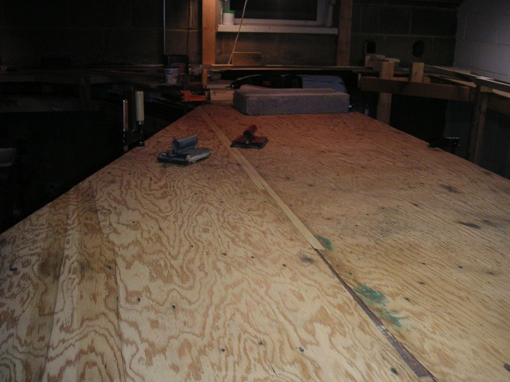
December 26, 2004
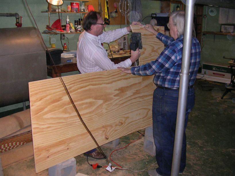
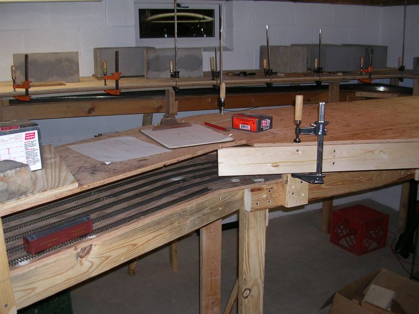
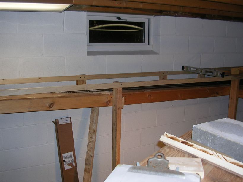
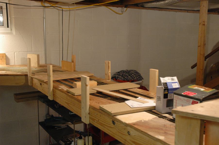
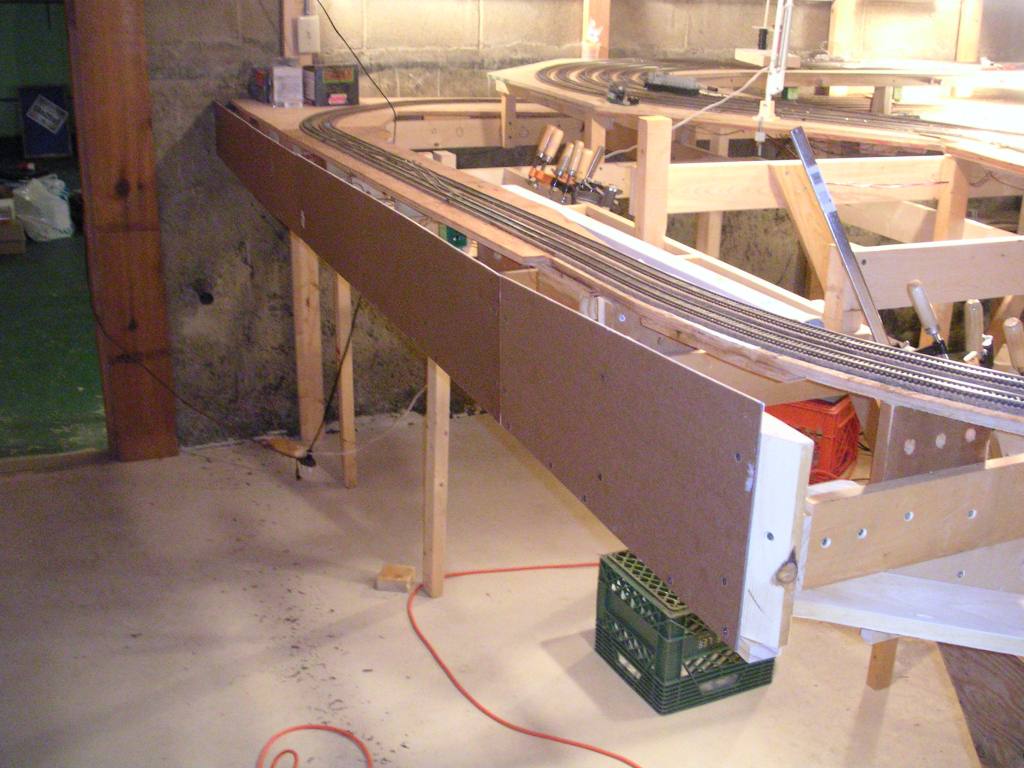
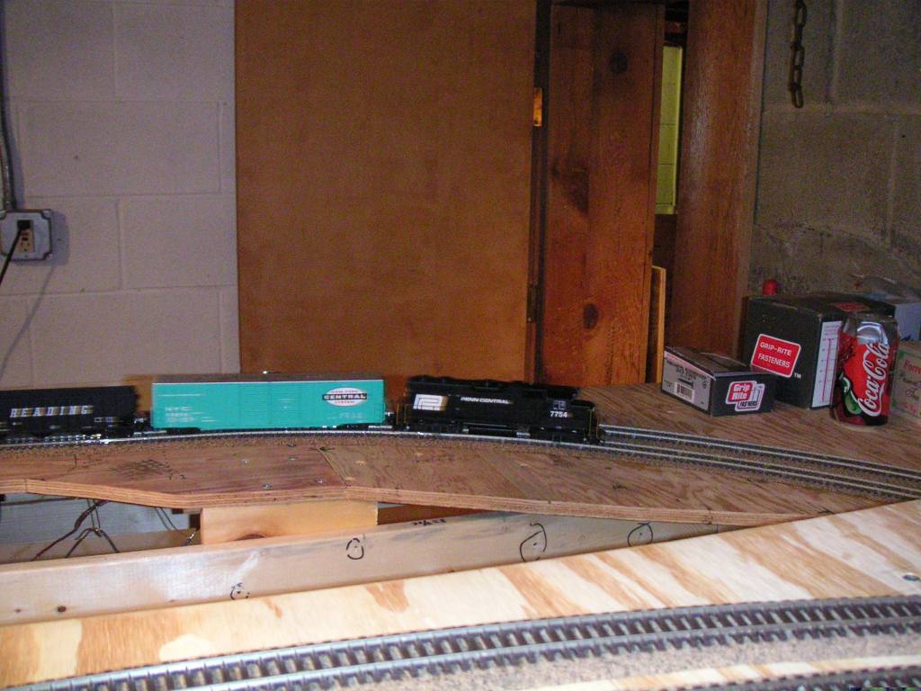
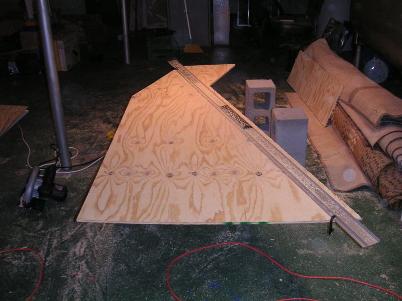 We spent this day cutting the rest of the plywood for the upper layer of plywood. Here is the piece that extends
from the Castle wye to Mahoning Avenue.
We spent this day cutting the rest of the plywood for the upper layer of plywood. Here is the piece that extends
from the Castle wye to Mahoning Avenue.
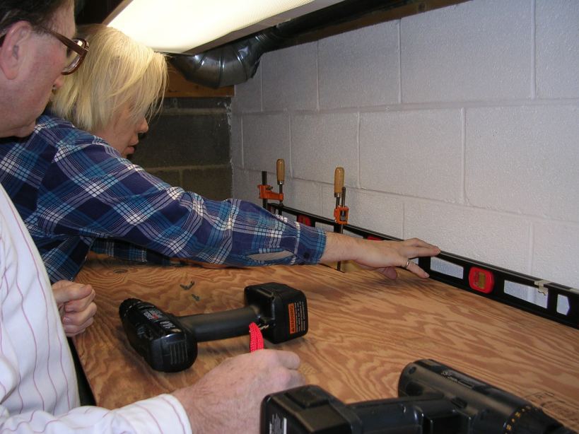
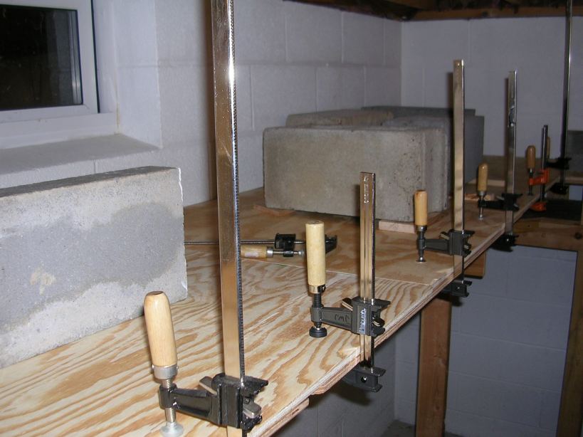
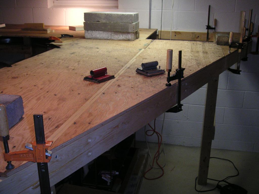
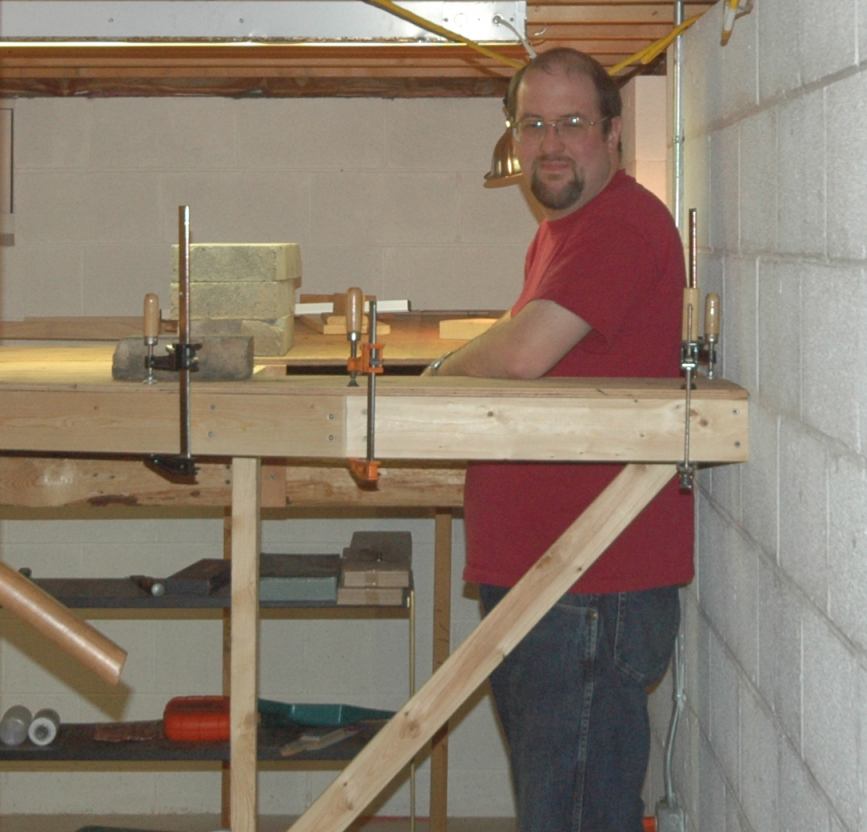
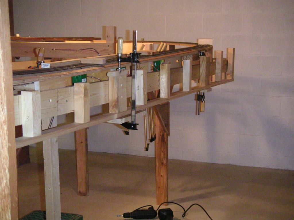
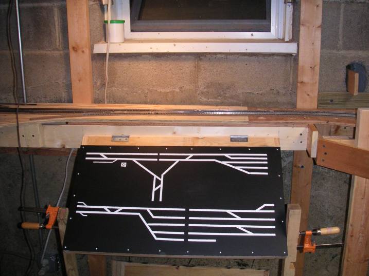
 We also glued down one section of plywood on the upper level. Here is that piece, held down with lots of clamps
and blocks.
We also glued down one section of plywood on the upper level. Here is that piece, held down with lots of clamps
and blocks.
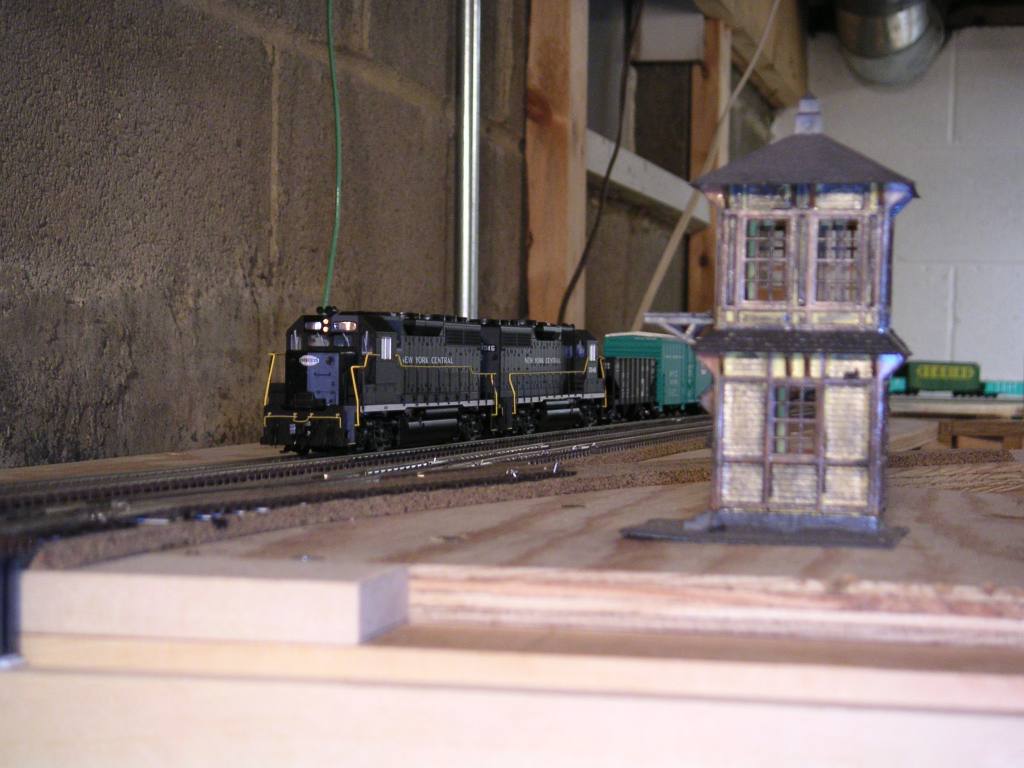
 Before covering over the staging yard completely, I decided to add rerailers to at least one end of the staging yard.
This was based on an idea I read about in a Model Railroader magazine article by Tony Koester. (Why didn't I
think of this months ago?)
Before covering over the staging yard completely, I decided to add rerailers to at least one end of the staging yard.
This was based on an idea I read about in a Model Railroader magazine article by Tony Koester. (Why didn't I
think of this months ago?)
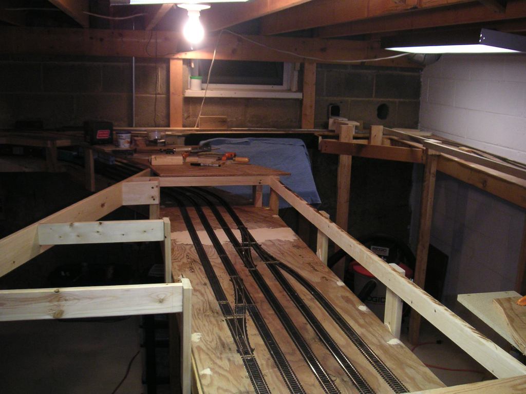
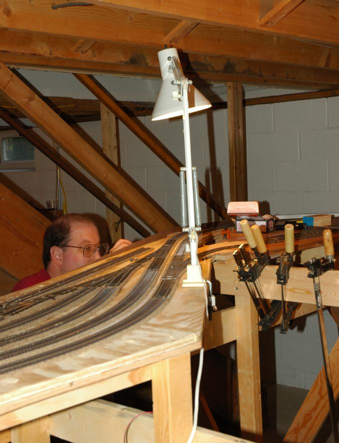
December 17, 2004
We began the upper layer of plywood on the upper level.
 The finished lower layer of plywood near the New Castle station area.
 Fred makes copious amount of sawdust while cutting a new sheet of plywood.
 Another cut sheet of plywood gets a cleanup with the sander by Blaine.
 Fred and Blaine check the grade on the upper level before test-fitting the next piece of plywood.
 Look at the carnage! That's a lot of sawdust!
 The new plywood is set in place, and held down with clamps and blocks to make it conform with the existing plywood.
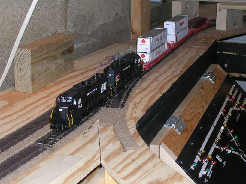
 For clearance reasons, the upper sheet of plywood extended a few inches closer towards the Castle wye.
Here, the test train was pulled out to check the clearances again.
For clearance reasons, the upper sheet of plywood extended a few inches closer towards the Castle wye.
Here, the test train was pulled out to check the clearances again.
 Clamps and blocks everywhere...
 The test train rolls past the Castle control panel as it heads back to Conway staging to be put away for the night.
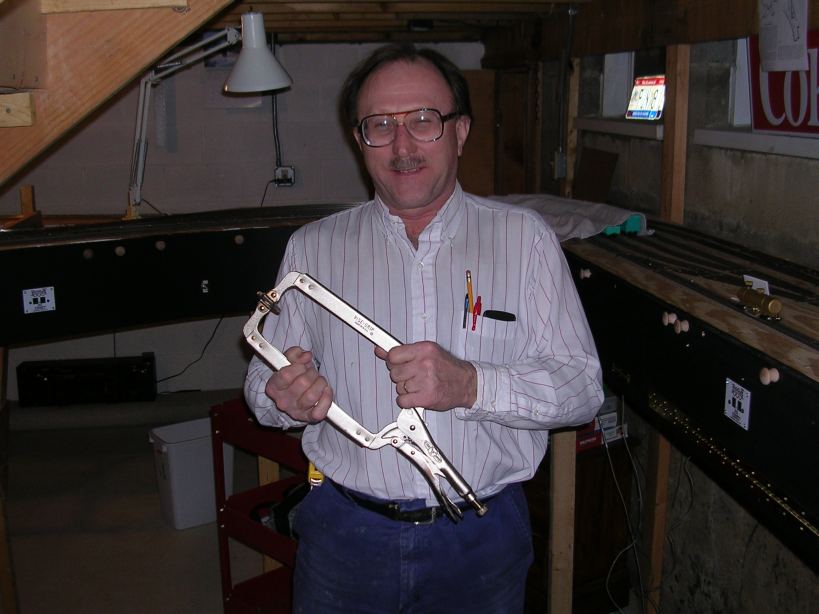 Blaine poses with a large clamp that we named "Widowmaker". It is useful for holding pieces of wood
while drilling pocket screw holes in it. The first time I saw that clamp, I had a painful mental picture which led me
to give it its name.
Blaine poses with a large clamp that we named "Widowmaker". It is useful for holding pieces of wood
while drilling pocket screw holes in it. The first time I saw that clamp, I had a painful mental picture which led me
to give it its name.
December 15, 2004
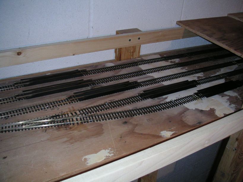
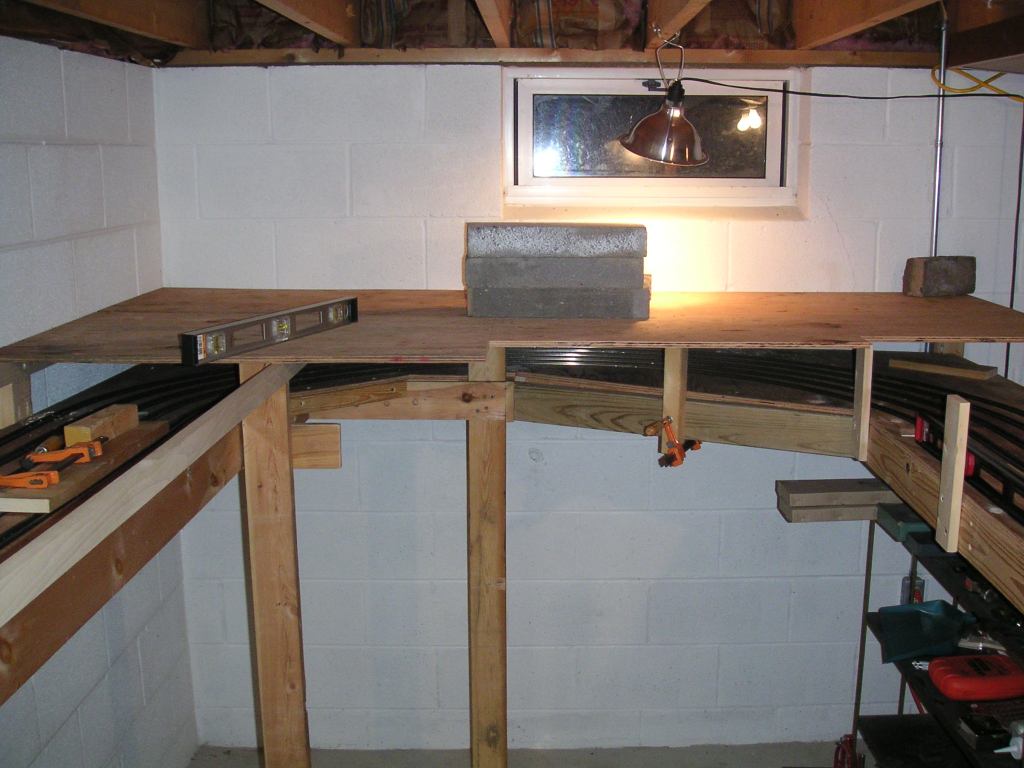
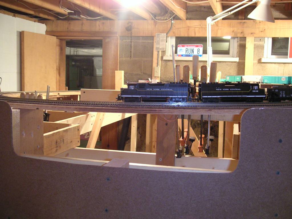
On this day, we finished the bottom layer of plywood for the upper level.
 This shows the benchwork at the north end of New Castle over top of the staging yard. The rail in the front is a 1x2.
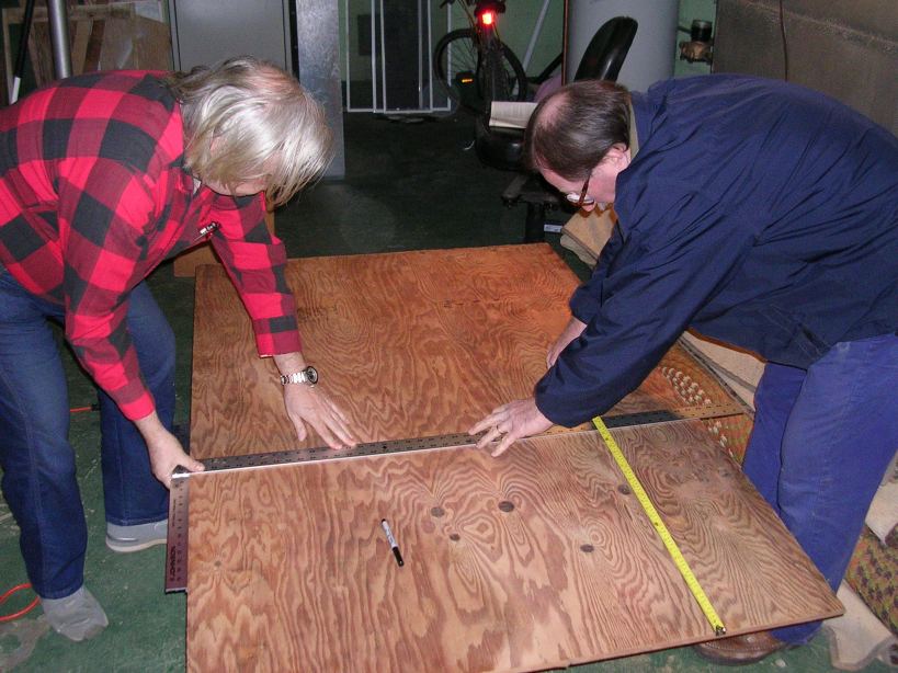 Fred and Blaine measure a piece of wood in preparation for cutting.
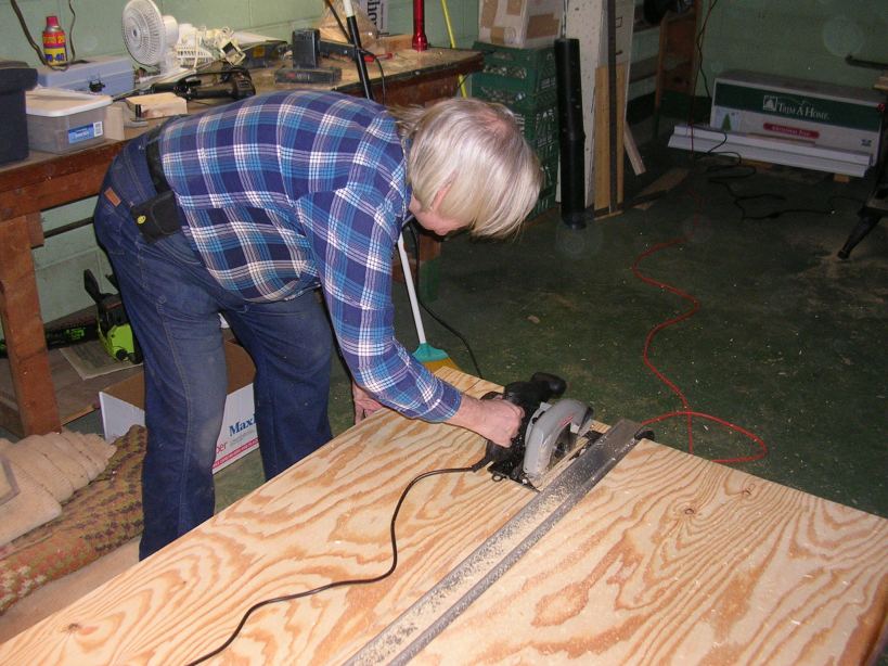
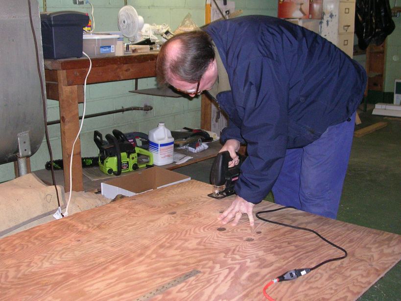 Blaine cuts the plywood with a sabre saw.
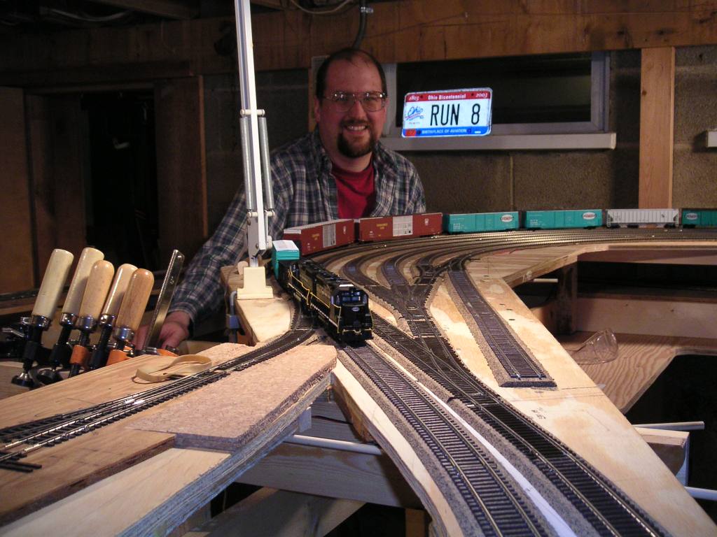
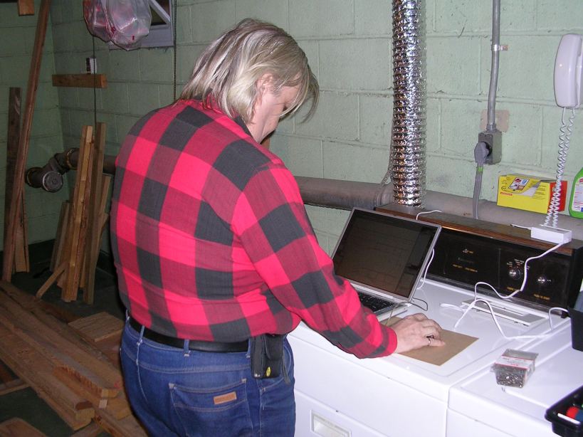 While Blaine is cutting, Fred checks the layout CAD drawings on his Powerbook.
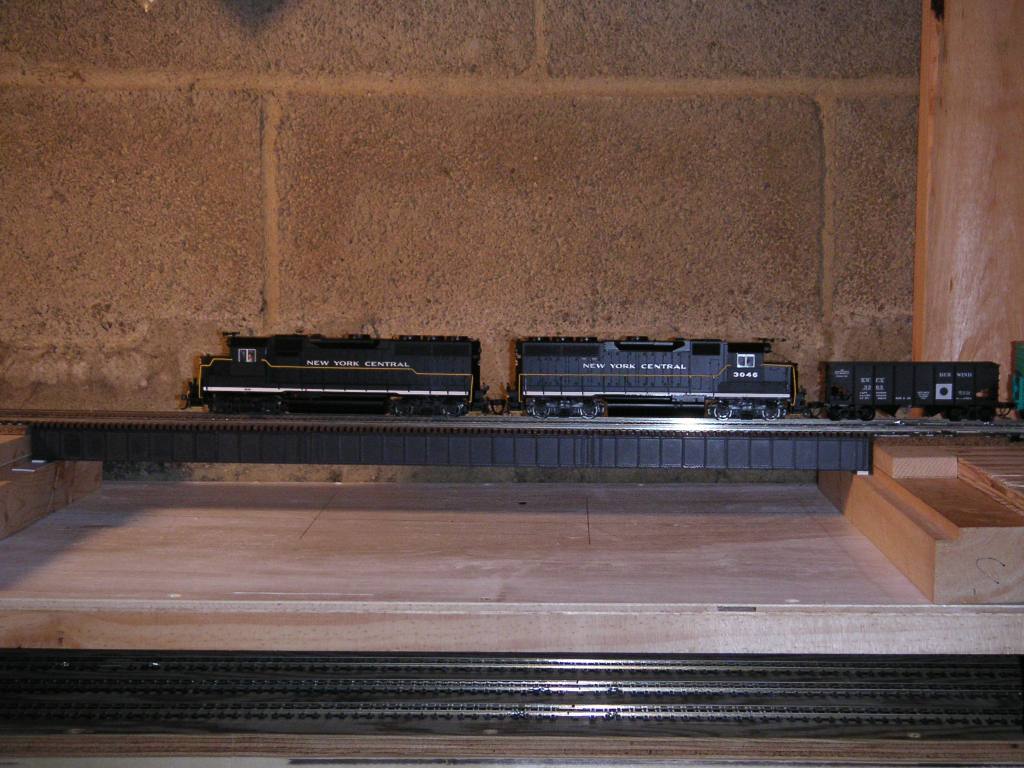
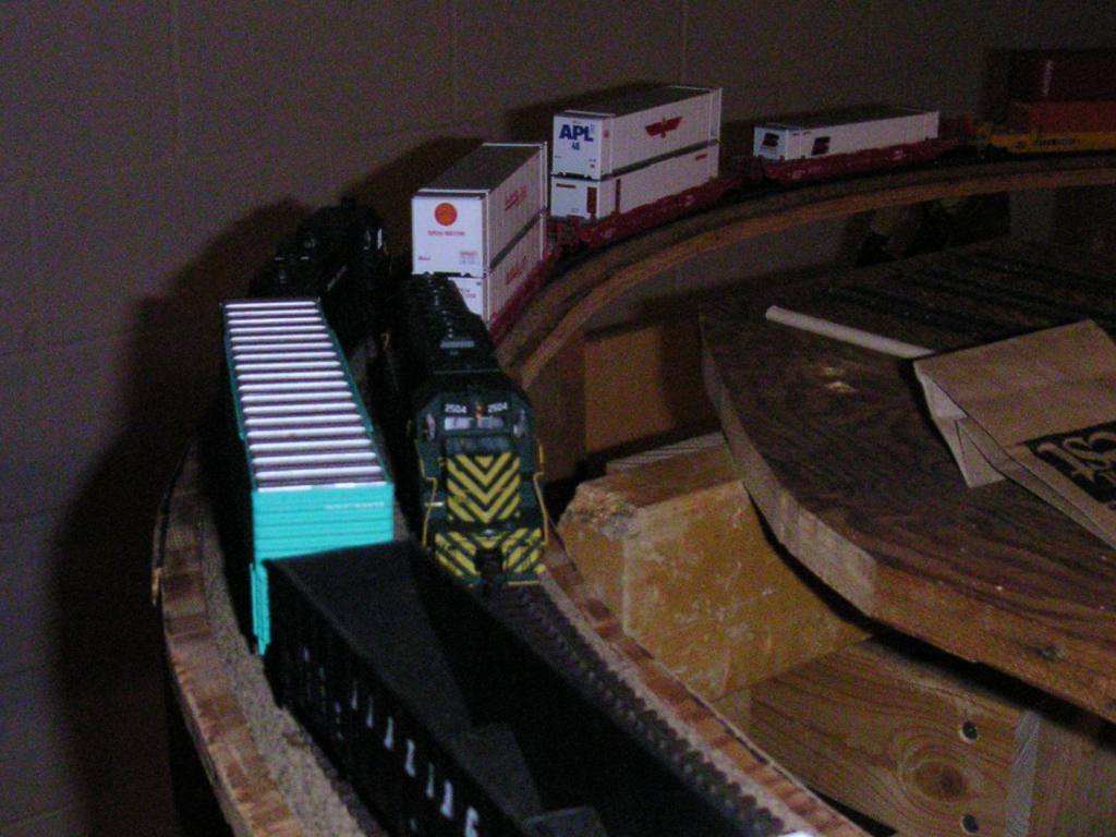
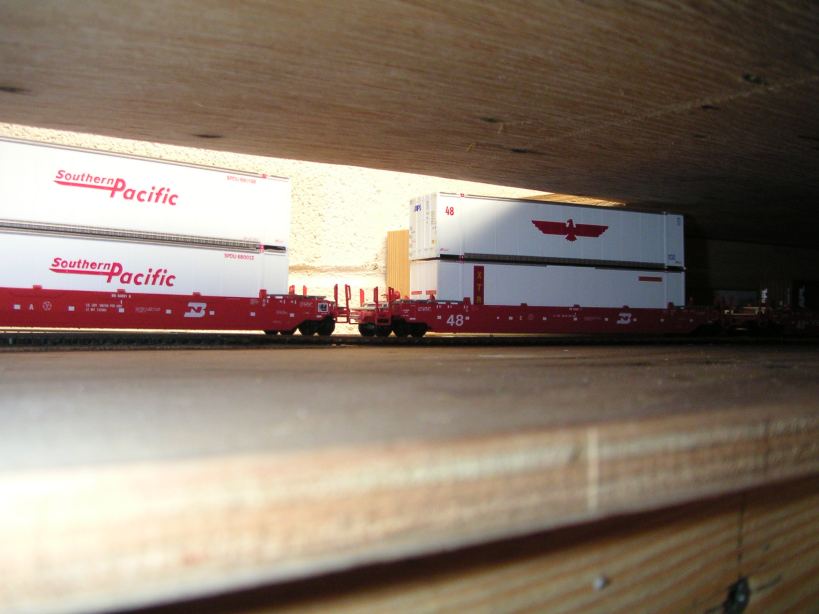 Checking the clearance of the double-stack test cars after the plywood is cut. They clear, but it's close!
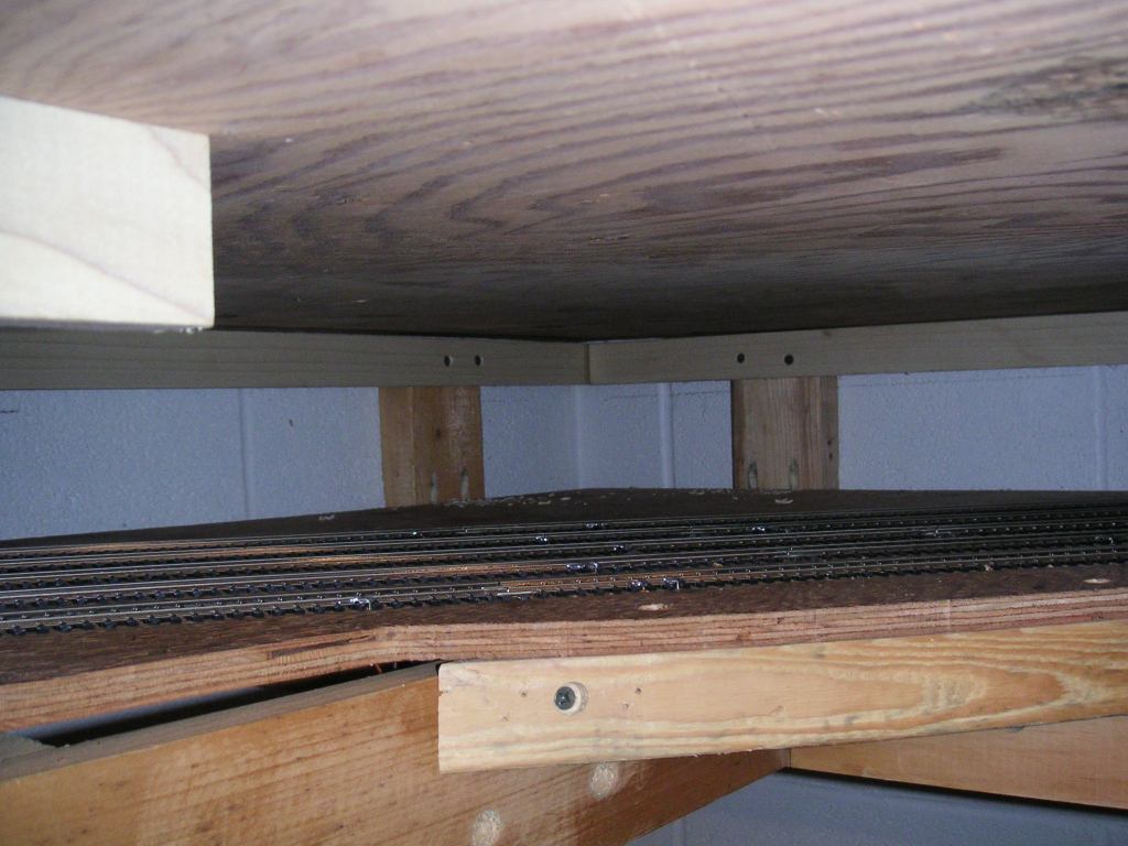
 Another view, from above, showing the clearance. The area where the cars are will be eventually covered over
with removable foam scenery.
Another view, from above, showing the clearance. The area where the cars are will be eventually covered over
with removable foam scenery.
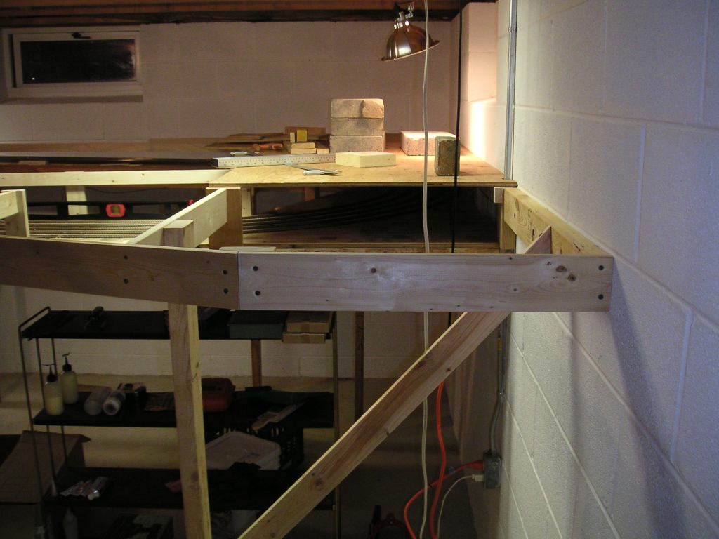
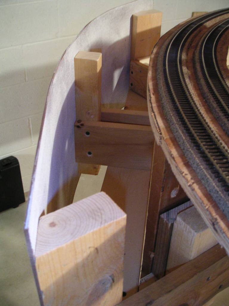
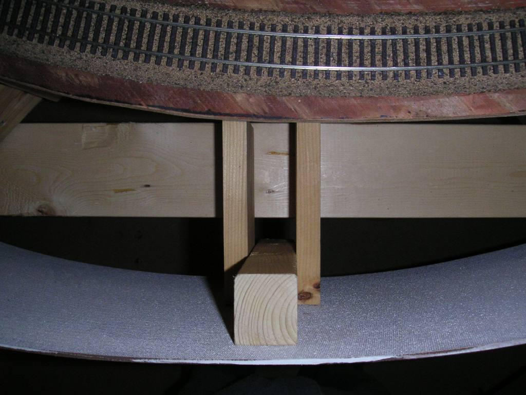
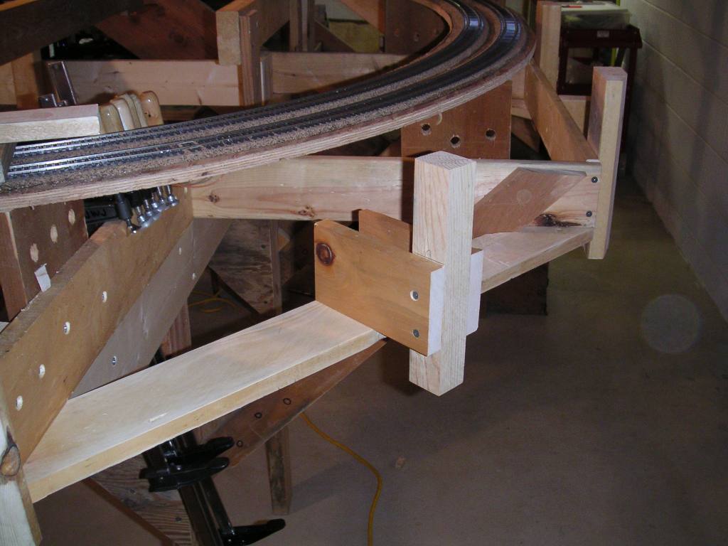
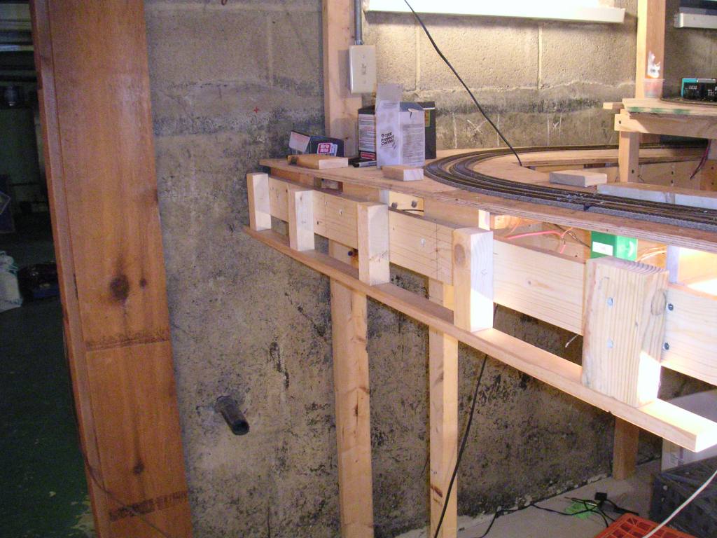
November 19, 2004
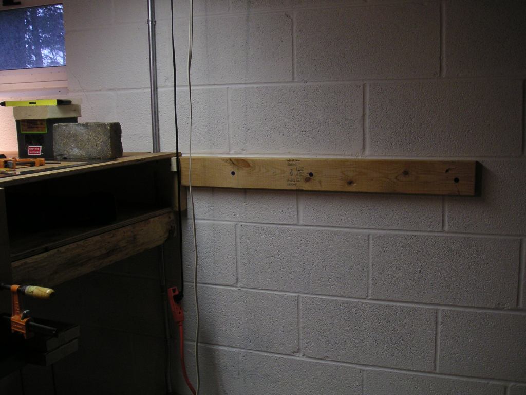 This day we constructed the benchwork and the bottom layer of plywood for the upper level between the Castle wye
and the New Castle freight station area. Here is the "before" picture: a 2x4 attached to the wall with tapcon screws.
This day we constructed the benchwork and the bottom layer of plywood for the upper level between the Castle wye
and the New Castle freight station area. Here is the "before" picture: a 2x4 attached to the wall with tapcon screws.
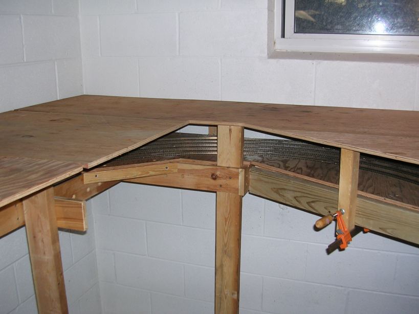
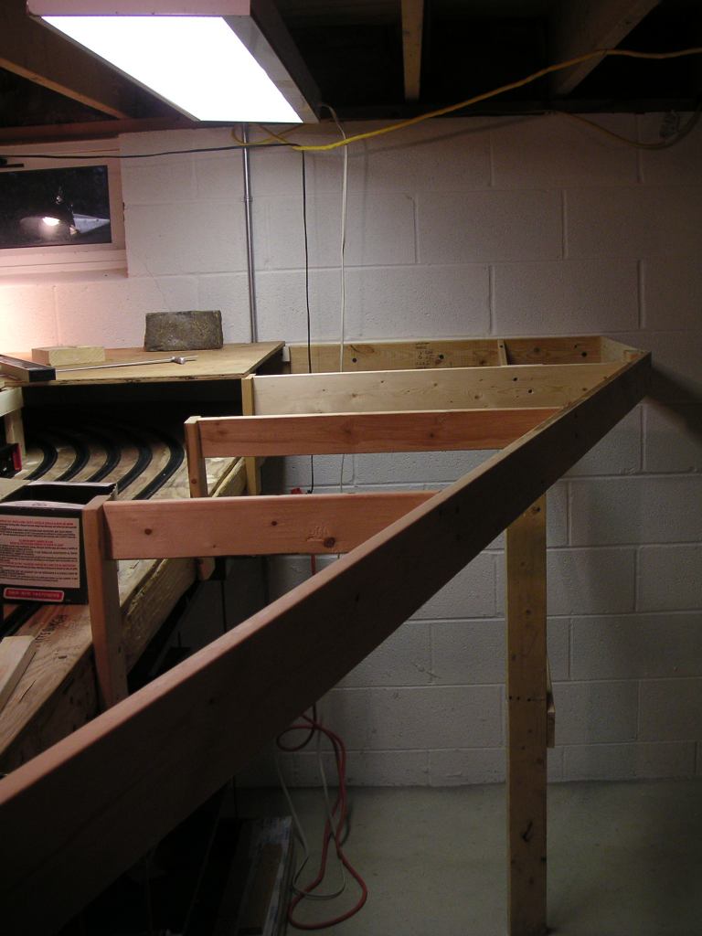 The first "after" picture: open grid benchwork between the wall and supports attached to the staging yard.
The plywood will go on the top of this. Noticed the recessed leg and the unimpeded access to the staging yard
from below.
The first "after" picture: open grid benchwork between the wall and supports attached to the staging yard.
The plywood will go on the top of this. Noticed the recessed leg and the unimpeded access to the staging yard
from below.
 This picture shows where the new benchwork was attached to the existing benchwork near the duckunder and the
Castle wye.
This picture shows where the new benchwork was attached to the existing benchwork near the duckunder and the
Castle wye.
 A side view of the new benchwork section. The E&P main will curve away from the camera, but the area
closest to the aisle will have a small industrial area, representing downtown New Castle industries served by
the Houston Secondary, originally the PRR-owned Western New York & Pennsylvania.
A side view of the new benchwork section. The E&P main will curve away from the camera, but the area
closest to the aisle will have a small industrial area, representing downtown New Castle industries served by
the Houston Secondary, originally the PRR-owned Western New York & Pennsylvania.
 A view back towards the Castle wye. The Pittsburgh crossovers in the staging yard are in the center of the picture.
 The same view, after the first layer of plywood is installed.
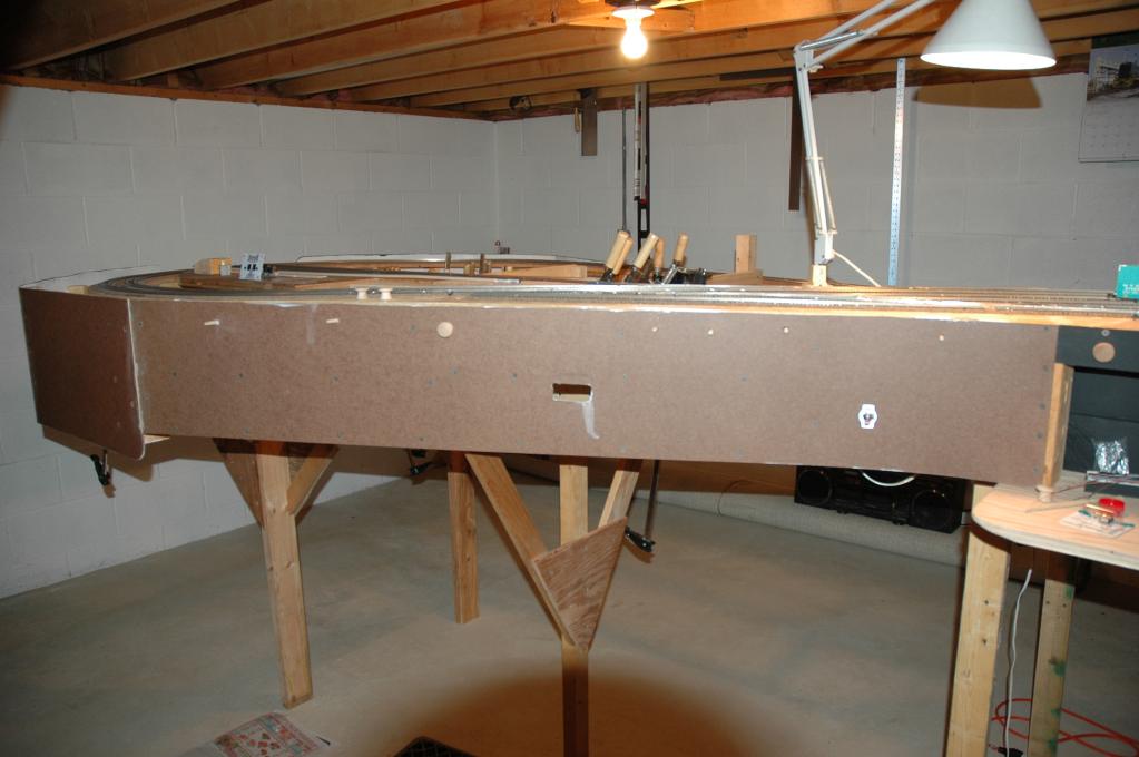
 The final "after" picture, with the first layer of plywood clamped into place. Like on other parts of this
layout, this section will be built using two layers of half-inch plywood to form a 1-inch layer which will be very strong
and require a minimum of support.
The final "after" picture, with the first layer of plywood clamped into place. Like on other parts of this
layout, this section will be built using two layers of half-inch plywood to form a 1-inch layer which will be very strong
and require a minimum of support.
 Here's me, in the middle of the benchwork. The place where I am standing will eventually be filled in with plywood
as well.
Here's me, in the middle of the benchwork. The place where I am standing will eventually be filled in with plywood
as well.
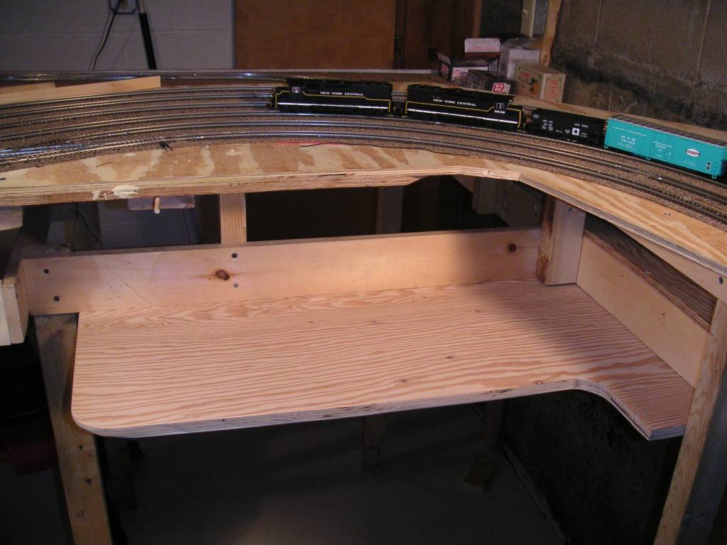
October 31, 2004
 Halloween was celebrating by setting in place the bottom layer of plywood for the upper level trackage near the
New Castle freight station. The blocks are to hold the wood down and help it to conform to the shape it will be
permanently attached in.
Halloween was celebrating by setting in place the bottom layer of plywood for the upper level trackage near the
New Castle freight station. The blocks are to hold the wood down and help it to conform to the shape it will be
permanently attached in.
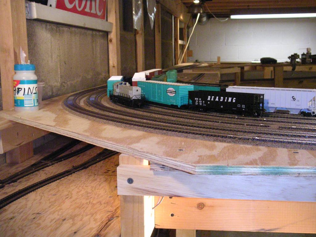
 A view into the newly-enclosed staging yard.
 Details of industrial sidings were being sketched out on a spare copy of the track plan.
October 03, 2004
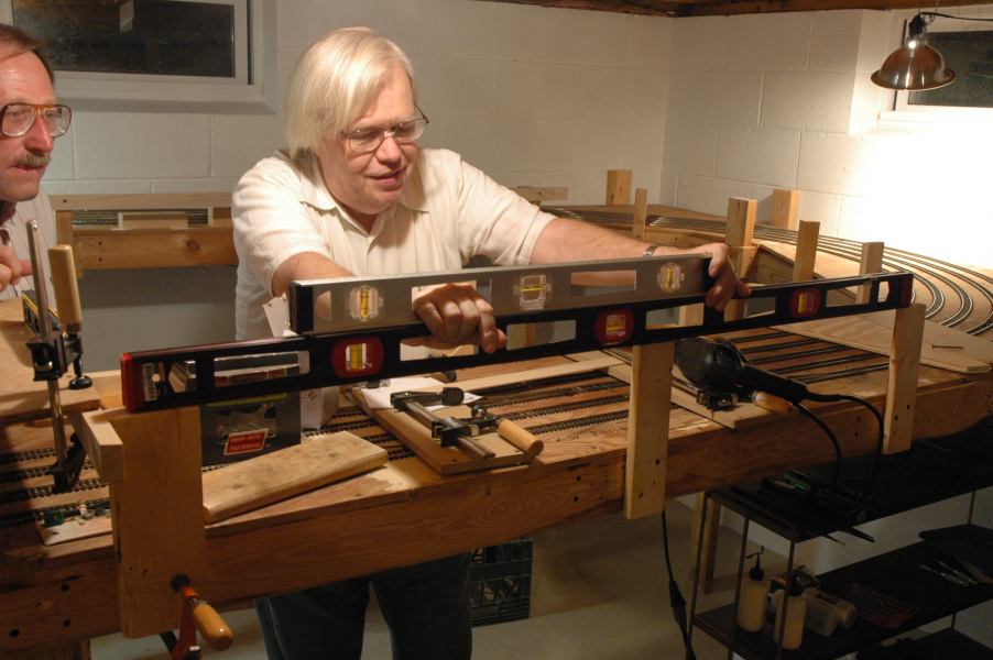
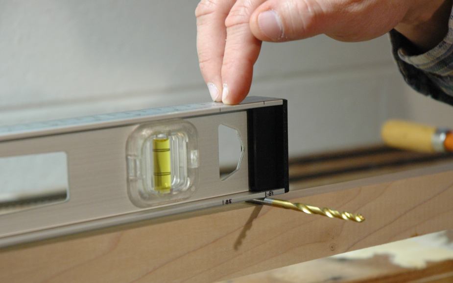
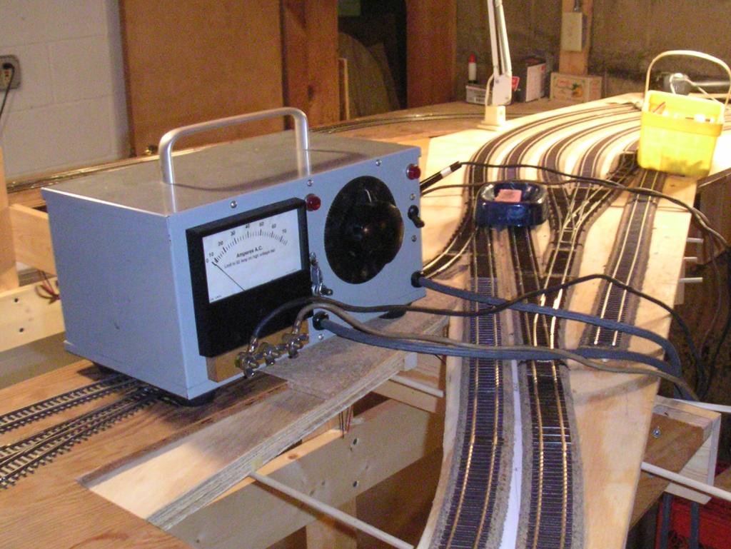
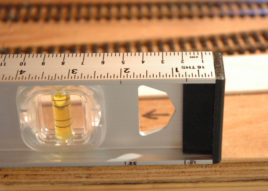 This picture shows how we measured grades while building the upper level of the E&P through New Castle. A drill bit was placed under the 2-foot level at the appropriate mark, and when the bubble in the level was centered, the desired grade was achieved.
 Fred demonstrates the above technique across two supports that will be used to support the upper level.
 Determining the grade around the curve near the New Castle freight station.
 Blaine had brought over an O scale boxcar he bought at the Berea train show the day before. Just for fun, we put
it on the tracks on the Mahoning River bridge. Surprisingly, the main lines there are spaced just right so that the
car would roll on the rails! We put one of my "suicide fleet" boxcars next to it for a size comparison.
Blaine had brought over an O scale boxcar he bought at the Berea train show the day before. Just for fun, we put
it on the tracks on the Mahoning River bridge. Surprisingly, the main lines there are spaced just right so that the
car would roll on the rails! We put one of my "suicide fleet" boxcars next to it for a size comparison.
 Blaine Hays works on cutting a piece of plywood for part of the upper level.
 We used the "drill bit technique" to check the grade along the 1x2 rail we ran as a support for the upper
plywood.
We used the "drill bit technique" to check the grade along the 1x2 rail we ran as a support for the upper
plywood.
 The finished support pieces for the upper level at the Pittsburgh staging yard crossovers and into the Youngstown
staging.
The finished support pieces for the upper level at the Pittsburgh staging yard crossovers and into the Youngstown
staging.
August 8, 2004
 Here is the completed facia board that was installed during the previous work session, awaiting paint. The facia will
be painted after the manual turnout pushrod controls are reinstalled.
Here is the completed facia board that was installed during the previous work session, awaiting paint. The facia will
be painted after the manual turnout pushrod controls are reinstalled.
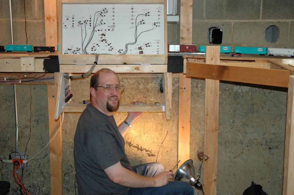
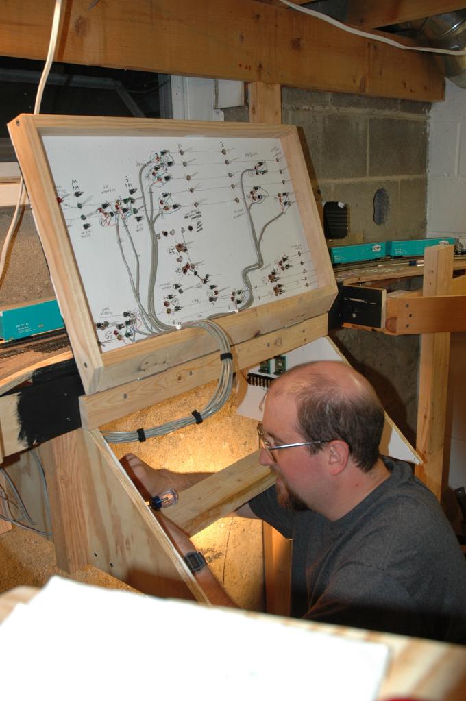 I spent most of this afternoon working on the Castle Tower control panel. Here I am working on attaching wires to
the NCE Switch-It stationary decoders inside the panel cabinet. The panel is hinged and is open here to allow
easier access.
I spent most of this afternoon working on the Castle Tower control panel. Here I am working on attaching wires to
the NCE Switch-It stationary decoders inside the panel cabinet. The panel is hinged and is open here to allow
easier access.
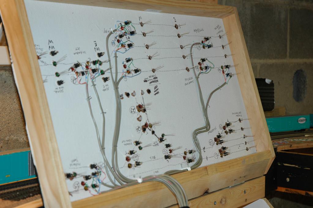 Detail of the wiring on the underside of the panel. I used a marker to make a crude outline of the markings on
the reverse side to aid me with the wiring. I've taken great pains to keep the wiring neat.
Detail of the wiring on the underside of the panel. I used a marker to make a crude outline of the markings on
the reverse side to aid me with the wiring. I've taken great pains to keep the wiring neat.
 That's me, hard at work on the wiring...
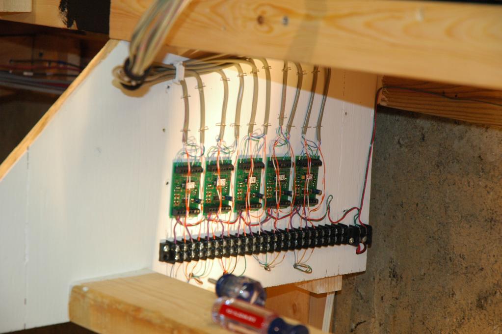 This is the mostly-completed switch wiring on the left side of the cabinet. There is one more Switch-It which will be
installed in the blank space on the right. Five wires are used for each turnout: two wires for the normal and reversed
pushbuttons, a common return wire for the pushbuttons, and two wires carrying Tortoise power to light the
switch position LEDs.
This is the mostly-completed switch wiring on the left side of the cabinet. There is one more Switch-It which will be
installed in the blank space on the right. Five wires are used for each turnout: two wires for the normal and reversed
pushbuttons, a common return wire for the pushbuttons, and two wires carrying Tortoise power to light the
switch position LEDs.
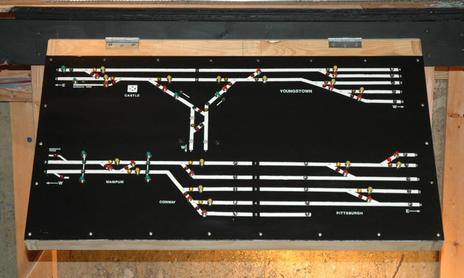 A closeup of the control panel. Some of the LEDs are lit, but you can't really tell from the picture.
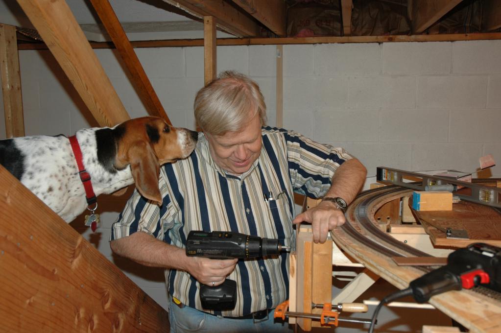
June 20, 2004
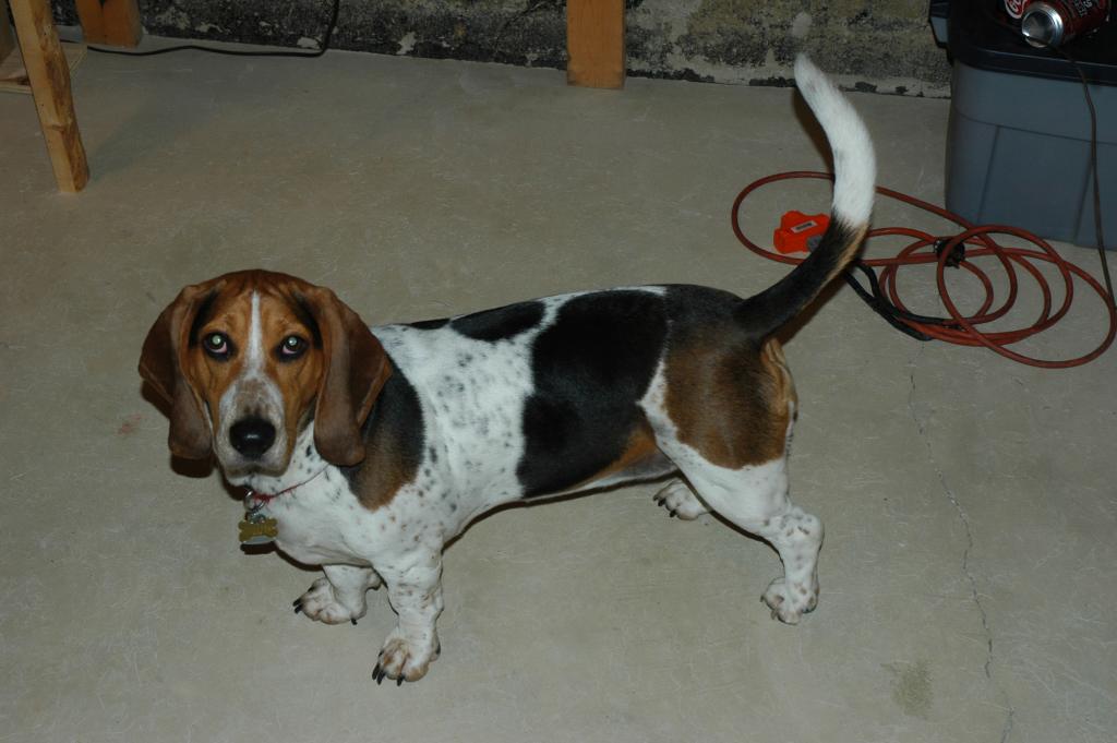 Fred and I had some help on this day. I was dogistting for my sister and brother-in-law that weekend, and this is
their dog, Maxine.
Fred and I had some help on this day. I was dogistting for my sister and brother-in-law that weekend, and this is
their dog, Maxine.
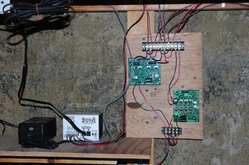 The Digitrax DCC command station (left) and the Master Power Board (right).
 Here is the completed facia board along the west end of Moravia Yard. The facia board has doors in it which fold down to allow access to the staging yards for the inevitable derailments that will someday occur.
 Another view of the facia board, showing an open door. This not only hides the staging yard, but makes gives the front
of the layout a finished appearance. The green board attached to the door is a Digitrax UP-5 panel.
Another view of the facia board, showing an open door. This not only hides the staging yard, but makes gives the front
of the layout a finished appearance. The green board attached to the door is a Digitrax UP-5 panel.
 Yours truly, cutting some Masonite for the facia board at the east end of Moravia Yard. Always wear eye protection
when using power tools.
Yours truly, cutting some Masonite for the facia board at the east end of Moravia Yard. Always wear eye protection
when using power tools.
 While I was cutting the Masonite, Fred worked on installing support brackets for the facia board, under close
supervision from Maxine.
While I was cutting the Masonite, Fred worked on installing support brackets for the facia board, under close
supervision from Maxine.
 Here's me working on attaching the facia board to the layout at the east end of Moravia Yard.
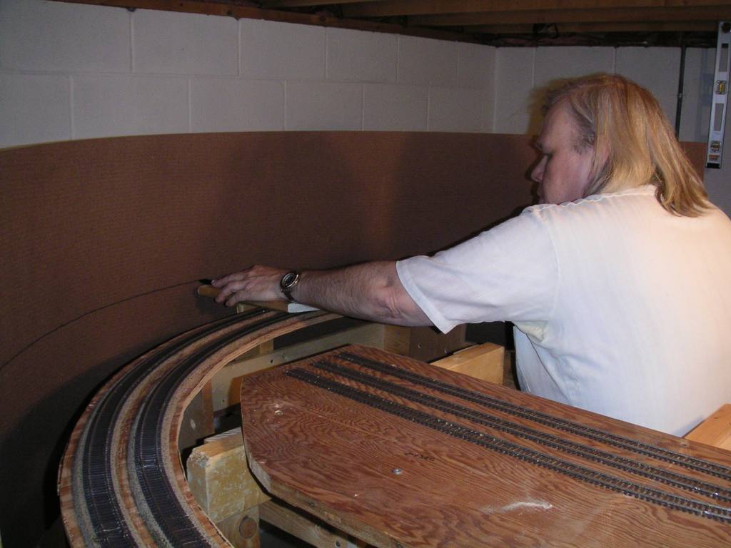
April 25, 2004
 Some of the finished facia board, ending near the Mahoning Valley Sand & Gravel plant. The angle-cut 2x4 will be
used to attach the next piece of facia board to. The missing facia in the right background has been cut out in an area
where the scenery will drop below track level at an overpass over a road.
Some of the finished facia board, ending near the Mahoning Valley Sand & Gravel plant. The angle-cut 2x4 will be
used to attach the next piece of facia board to. The missing facia in the right background has been cut out in an area
where the scenery will drop below track level at an overpass over a road.
 Looking down on where the facia board attaches to the bracing.
 To celebrate a job well done, we decided to have some fun running some trains around the staging yard and the
E&A main line. Two Atlas Master GP40s in New York Central colors pull an expanded test train past a stand-in
for Castle Tower.
To celebrate a job well done, we decided to have some fun running some trains around the staging yard and the
E&A main line. Two Atlas Master GP40s in New York Central colors pull an expanded test train past a stand-in
for Castle Tower.
 The test train crosses the Mahoning River bridge. Do they look great or what? Below the future riverbed, the
tracks of the staging yard can be seen. Yes, the clearance down there is tight...more on that later.
The test train crosses the Mahoning River bridge. Do they look great or what? Below the future riverbed, the
tracks of the staging yard can be seen. Yes, the clearance down there is tight...more on that later.
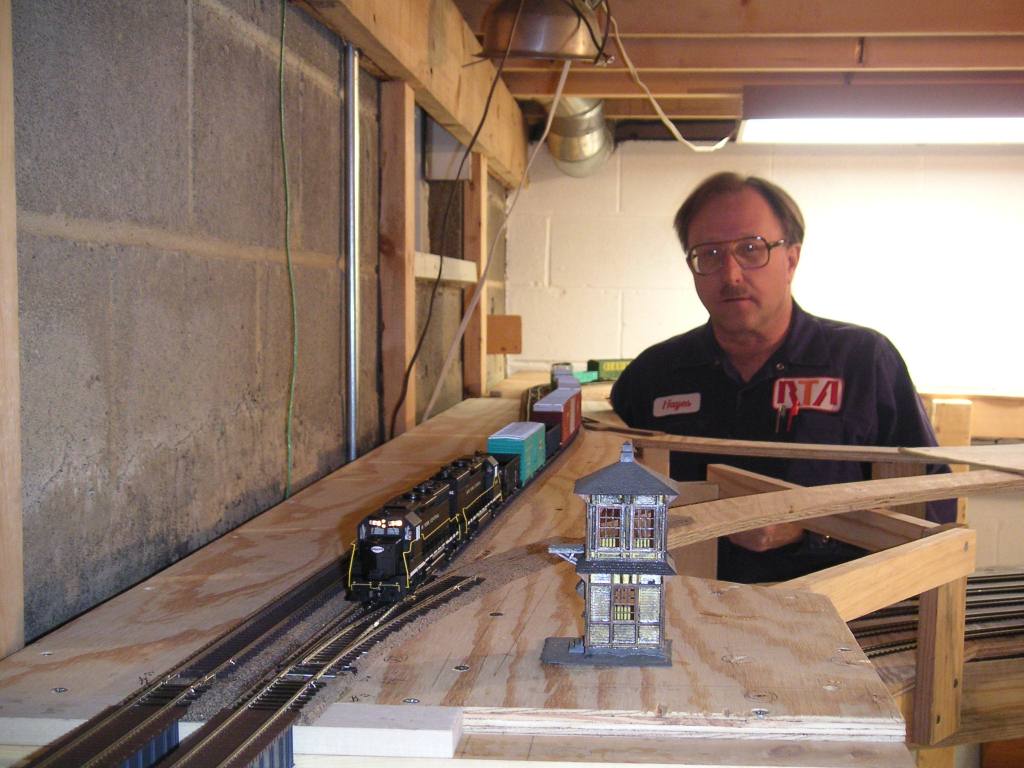
 The happy basement owner, with the freight train passing Moravia Yard in the foreground. The license plate in the
background used to be on my old Chevy Beretta before I sold it last year.
The happy basement owner, with the freight train passing Moravia Yard in the foreground. The license plate in the
background used to be on my old Chevy Beretta before I sold it last year.
 Between Moravia Yard and Wampum Junction, the facia board was cut out where the tracks will pass over a
creek and a road, roughly modeled after this one on the prototype, where PA Route
168 goes under the former E&A (now the NS Youngstown Line). Cutting out the facia board will allow a
viewer to better see the overpass and the road.
Between Moravia Yard and Wampum Junction, the facia board was cut out where the tracks will pass over a
creek and a road, roughly modeled after this one on the prototype, where PA Route
168 goes under the former E&A (now the NS Youngstown Line). Cutting out the facia board will allow a
viewer to better see the overpass and the road.
 Crossing over at Wampum Junction. This will look so much better once we get scenery and signals...
 Blaine "Purple" Hays takes a turn at the throttle as he watches the train pass the wye at Castle.
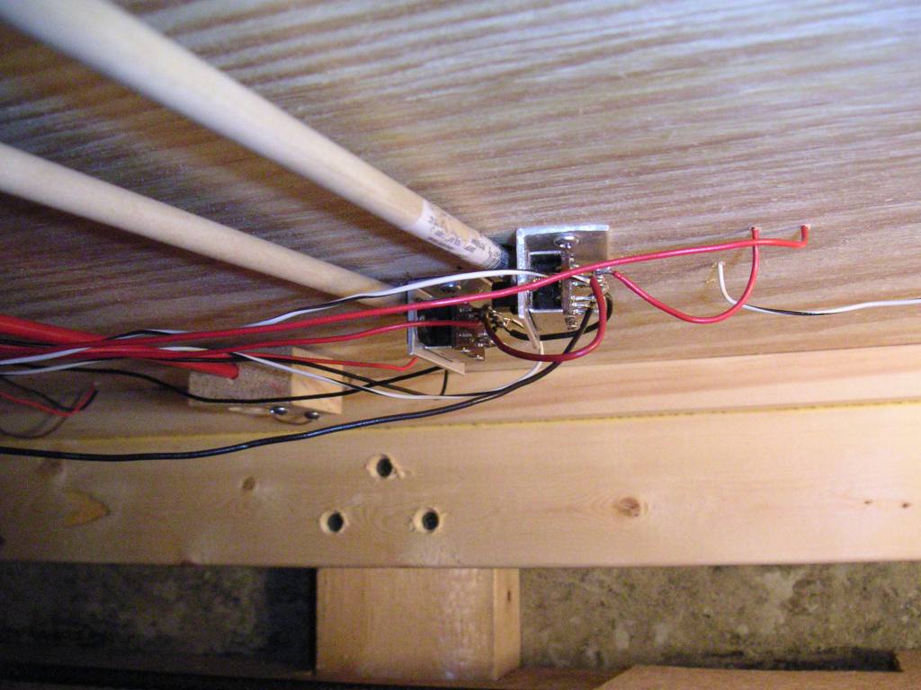
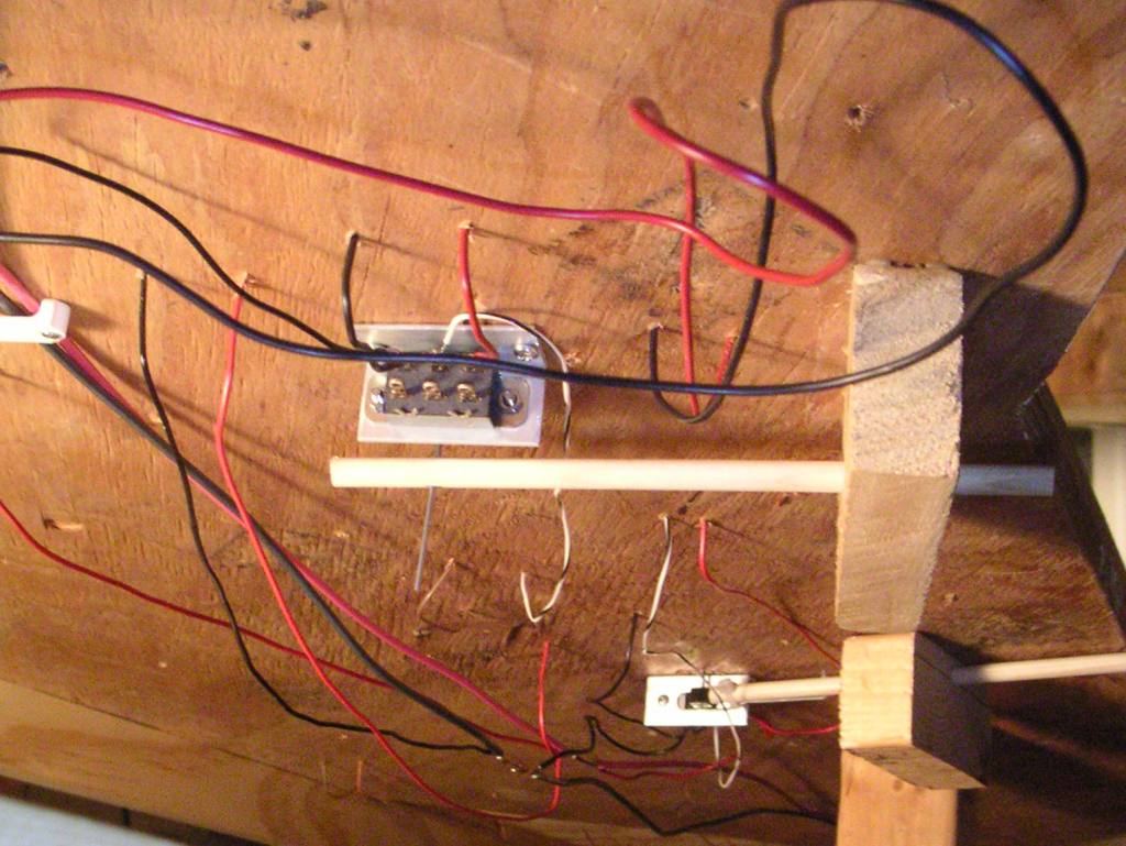
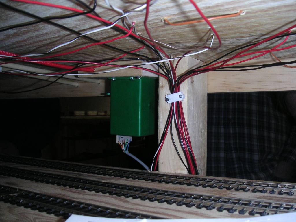 This picture demonstrates the benefits of a small digital camera. It was taken from inside the staging yard, looking out
at the aisle. Here you can see the feeder wires that come up the inside of the support and were fed through the wire
staple before going to various tracks and turnout switches.
This picture demonstrates the benefits of a small digital camera. It was taken from inside the staging yard, looking out
at the aisle. Here you can see the feeder wires that come up the inside of the support and were fed through the wire
staple before going to various tracks and turnout switches.
 After we had some fun, we also built and installed this yardmaster's desk at Moravia Yard. Placing switchlists,
car cards, pop cans, pencils, uncoupling tools, coffee cups, etc., on the layout surface will be forbidden, so part of
the layout design involves creating enough places around the layout to properly place such paraphanelia. This
desk is large enough for a yardmaster or train crew to lay out their car cards or switch list while they work.
After we had some fun, we also built and installed this yardmaster's desk at Moravia Yard. Placing switchlists,
car cards, pop cans, pencils, uncoupling tools, coffee cups, etc., on the layout surface will be forbidden, so part of
the layout design involves creating enough places around the layout to properly place such paraphanelia. This
desk is large enough for a yardmaster or train crew to lay out their car cards or switch list while they work.
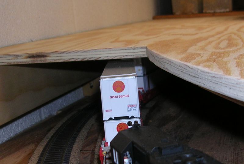
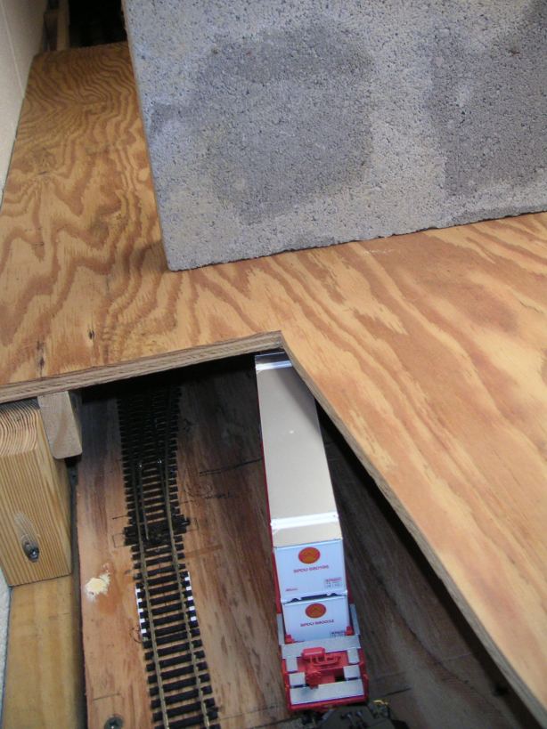
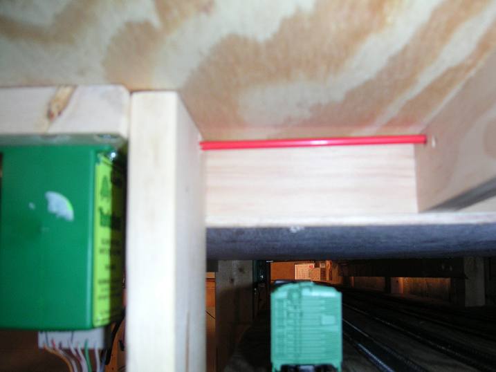
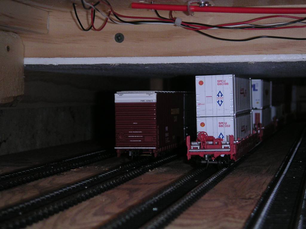 About that low clearance underneath the Mahoning River...here is photographic proof of it. The double-stack cars
clear by less than a quarter-inch. The high-cube boxcar has some more room to spare. At the very top of the picture
is the airplane control rod which remotely controls turnout 24.
About that low clearance underneath the Mahoning River...here is photographic proof of it. The double-stack cars
clear by less than a quarter-inch. The high-cube boxcar has some more room to spare. At the very top of the picture
is the airplane control rod which remotely controls turnout 24.
April 18, 2004
 We continued around the corner from Wampum Junction with the facia board. Here was the framework built at part of the
corner to hold up the facia board. The facia board needs good support for when tired operators try to lean on it.
We continued around the corner from Wampum Junction with the facia board. Here was the framework built at part of the
corner to hold up the facia board. The facia board needs good support for when tired operators try to lean on it.
 Fred marks the cut line on the Masonite sheet that will be used for the next section of facia board.
April 4, 2004
 The afternoon of 04/04/04 was spent on more facia board work. Here is the rest of the facia board framework at Wampum Junction.
 Those turnouts I had to wire at the west end of Moravia? I successfully wired them.
 The completed facia board along Wampum Junction.
March 28, 2004
 More wiring and turnout installation at Moravia Yard. Here were the switches for two turnouts at the west end of the yard. Because they ended up so close together, guess who got to wire them? Seems like everything is made in China anymore...
 Facia board installation was also in the works this day. This wooden framing at Wampum Junction will hold the facia board on the front of the layout.
March 21, 2004
 An undecorated Atlas Classic RS1 pulls a cut of test train cars into the west end of Moravia Yard. We spent this
session wiring the yard and install more pushrod turnouts.
An undecorated Atlas Classic RS1 pulls a cut of test train cars into the west end of Moravia Yard. We spent this
session wiring the yard and install more pushrod turnouts.
 Two examples of how to do pushrod turnouts. The turnout in the front has the pushrod ending a distance below the slide part of the electrical switch. The far turnout has the rod closer. We found that there was just enough give in the hole drilled through the switch that the rod would cause the points of the turnout to wiggle open enough for a car to pick a point and derail. As a result, the near turnout will be redone like that far one when we get to installing the facia board in this area.
 We were calculating track capacities at Moravia Yard, and moving cars around with the RS1.
 We also tested clearances. Yes, two 86-foot high cubes will clear each other on the inside yard tracks, but they look so ridiculous that their presence on those tracks will be banned via the employee timetable in the car restrictions section.
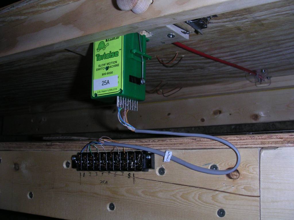
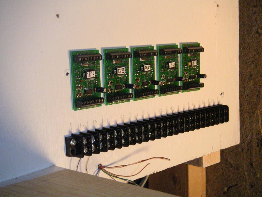 A group of NCE Switch-It stationary decoders mounted inside the control panel cabinet. They will be wired to the terminal strip, which will be attached on the other side to wires carrying the turnout power to the turnouts in the field. Wires to attach to control buttons will come in to the top and be wired up to the control panel.
March 7, 2004
 This is an underside view of the turnout linkage for the switch leading into the east end of Moravia Yard off of
mainline track 2. This pushrod uses a bell crank to reverse the normal direction of the throw. Ideally, the normal
position of a switch has the pushrod pushed in towards the layout, so that operators don't catch themselves on the
pushrod handle as they pass by. Sometimes, though, the usual position of the turnout would require the pushrod to
be pulled out if it was attached directly to the switch. The bell crank reverses the motion so that when the pushrod
handle is pulled out, it throws the switch to the reverse position, which is with the points away from the aisle.
This is an underside view of the turnout linkage for the switch leading into the east end of Moravia Yard off of
mainline track 2. This pushrod uses a bell crank to reverse the normal direction of the throw. Ideally, the normal
position of a switch has the pushrod pushed in towards the layout, so that operators don't catch themselves on the
pushrod handle as they pass by. Sometimes, though, the usual position of the turnout would require the pushrod to
be pulled out if it was attached directly to the switch. The bell crank reverses the motion so that when the pushrod
handle is pulled out, it throws the switch to the reverse position, which is with the points away from the aisle.
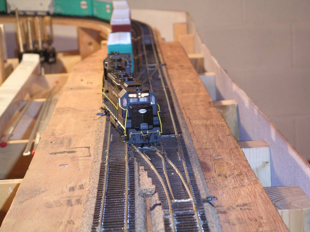
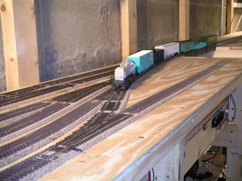
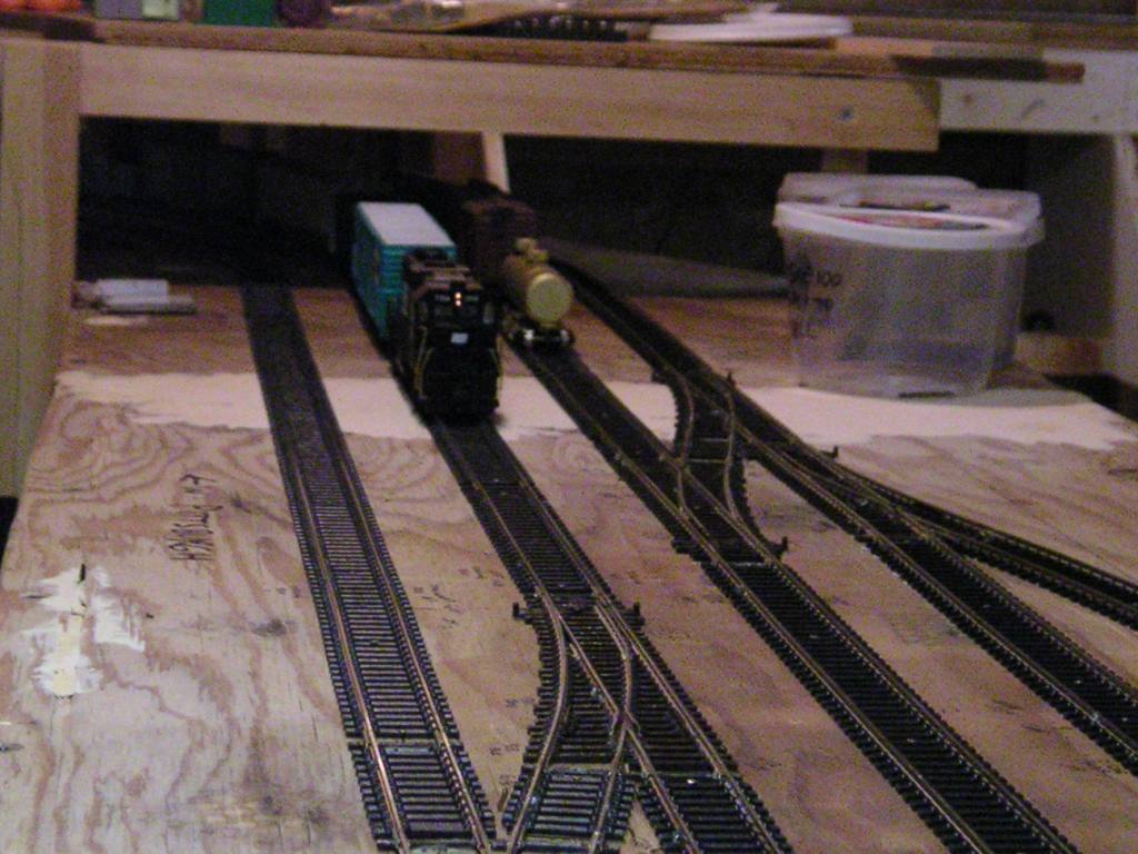 Here we go! The historic first run completely around the staging yard and on the E&A main line is about to begin,
as PC GP38 (an Atlas Master model) leads the freight car test train through the staging yard at the Pittsburgh
crossovers.
Here we go! The historic first run completely around the staging yard and on the E&A main line is about to begin,
as PC GP38 (an Atlas Master model) leads the freight car test train through the staging yard at the Pittsburgh
crossovers.
 The test train completes its first run as it passes Wampum Junction and enters the staging yard.
 Later on we got really brave and ran two trains at once! The stack car test train, powered by a Jersey Central
SD35 (another Atlas Master model) passes the freight car test train east of Moravia Yard.
Later on we got really brave and ran two trains at once! The stack car test train, powered by a Jersey Central
SD35 (another Atlas Master model) passes the freight car test train east of Moravia Yard.
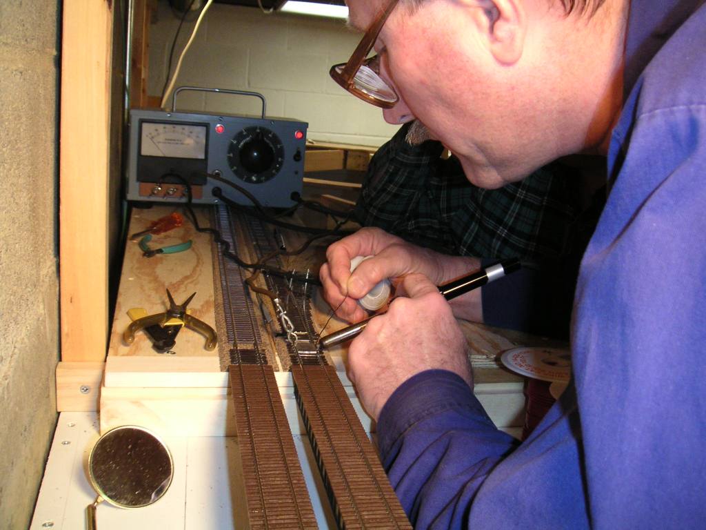
 This is Fred's resistance soldering setup. The gray box houses the transformer power supply. The soldering iron
item is behind the power unit.
This is Fred's resistance soldering setup. The gray box houses the transformer power supply. The soldering iron
item is behind the power unit.
 Here is a view of my track cleaning car, a CMX+ Clean Machine from Tony's Train Exchange. It uses a cleaning solvent (I used denatured alcohol) in the tank
and a pad on the bottom to scrub the track clean as it gets pushed around the layout by a locomotive.
Here is a view of my track cleaning car, a CMX+ Clean Machine from Tony's Train Exchange. It uses a cleaning solvent (I used denatured alcohol) in the tank
and a pad on the bottom to scrub the track clean as it gets pushed around the layout by a locomotive.
February 8, 2004
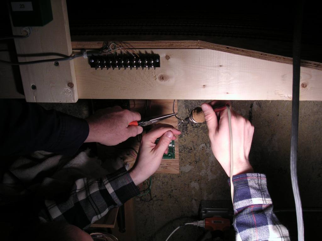 It's the three-handed soldering monster! No, actually it's me soldering a terminal to the end of a bus wire,
with Blaine Hays lending a hand to hold the wire still.
It's the three-handed soldering monster! No, actually it's me soldering a terminal to the end of a bus wire,
with Blaine Hays lending a hand to hold the wire still.
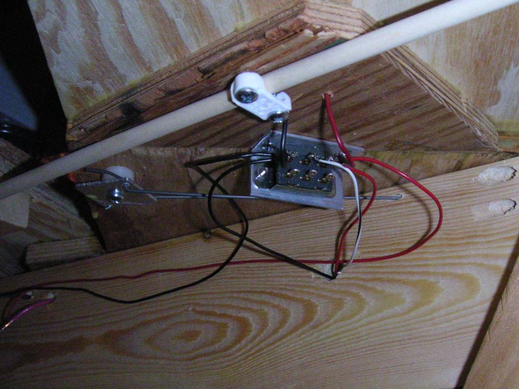
 This view of the Tortoise for turnout 25A shows how the remote Tortoise mounts worked. The Tortoise is mounted
to a 1x4 block, with a slot cut for the throw wire. The Gold-N-Rod airplane control rod enters the side of the block
through a 1/4" hole and the throw wire goes through it. On the right side of the picture, two plastic mounts
hold the control rod in position underneath the turnout. These mounts are made of pieces cut from a plastic edge
protector, used on corners of walls and furniture. The mounts are cut from the edge protector strip, drilled, and then
the corners are rounded off to prevent blood from getting on the tracks when the layout owner cuts his hand open on
the sharp corner while reaching into the staging yard to clean the track or rerail a car.
This view of the Tortoise for turnout 25A shows how the remote Tortoise mounts worked. The Tortoise is mounted
to a 1x4 block, with a slot cut for the throw wire. The Gold-N-Rod airplane control rod enters the side of the block
through a 1/4" hole and the throw wire goes through it. On the right side of the picture, two plastic mounts
hold the control rod in position underneath the turnout. These mounts are made of pieces cut from a plastic edge
protector, used on corners of walls and furniture. The mounts are cut from the edge protector strip, drilled, and then
the corners are rounded off to prevent blood from getting on the tracks when the layout owner cuts his hand open on
the sharp corner while reaching into the staging yard to clean the track or rerail a car.
 Blaine Hays makes a solder joint for a track feeder wire at the west end of the Mahoning River bridge. The turnout
being soldered to will eventually lead to the E&P Branch heading into downtown New Castle and beyond.
Blaine Hays makes a solder joint for a track feeder wire at the west end of the Mahoning River bridge. The turnout
being soldered to will eventually lead to the E&P Branch heading into downtown New Castle and beyond.
February 1, 2004
Super Bowl Sunday was spent in the basement while listening to the first half of the game on the radio. Lots of jumper wiring and working on manual turnouts on this day.
 Fred's camera sometimes has trouble figuring out where to focus. Here's an example. This is a remotely-mounted
power turnout control for turnout 23 at Castle Tower. The Tortoise is mounted a 1x4 block with a slot cut in it for the throwbar
to move in. Drilled in from the side is a 3/16" hole for the red tube, which is a
Gold-N-Rod model airplane control
rod, made by Sullivan Products. The other end of the rod is positioned under the turnout, where a length of piano
wire is inserted through the throwbar and into a hole drilled into the rod. The red tube is actually a sleeve that the nylon
control rod moves within; a slot in the tube under the turnout provides clearance for the throwbar piano wire, while the tube
is removed in the slot within the wood Tortoise block.
Fred's camera sometimes has trouble figuring out where to focus. Here's an example. This is a remotely-mounted
power turnout control for turnout 23 at Castle Tower. The Tortoise is mounted a 1x4 block with a slot cut in it for the throwbar
to move in. Drilled in from the side is a 3/16" hole for the red tube, which is a
Gold-N-Rod model airplane control
rod, made by Sullivan Products. The other end of the rod is positioned under the turnout, where a length of piano
wire is inserted through the throwbar and into a hole drilled into the rod. The red tube is actually a sleeve that the nylon
control rod moves within; a slot in the tube under the turnout provides clearance for the throwbar piano wire, while the tube
is removed in the slot within the wood Tortoise block.
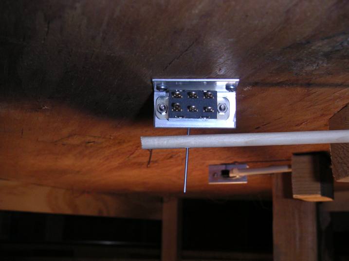
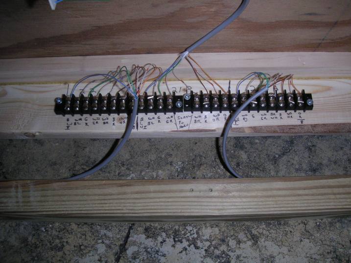 Terminal strips for Tortoise connections at the west end of Castle Tower. Left to right, these are for turnouts 22, 21B,
and 21A.
Terminal strips for Tortoise connections at the west end of Castle Tower. Left to right, these are for turnouts 22, 21B,
and 21A.
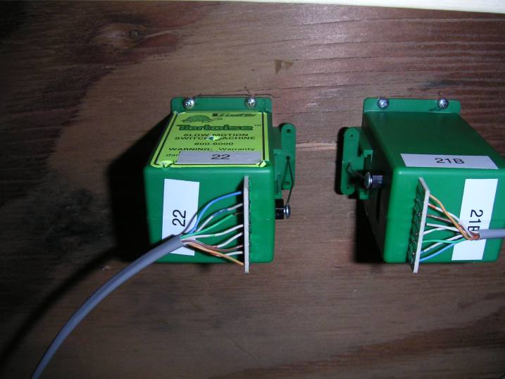 Yes, it is possible to mount Tortoises for turnouts that are mounted points-to-points...simply turn one Tortoise around.
These are the Tortoises for turnouts 22 and 21B at the west end of Castle Tower. Category 5 network cable is used to
connect the Tortoises to the terminal strips. It works well because it keeps the wires organized, and there are the same
numbers of conductors in Cat 5 cable as there terminals on the bottom of a Tortoise (eight).
Yes, it is possible to mount Tortoises for turnouts that are mounted points-to-points...simply turn one Tortoise around.
These are the Tortoises for turnouts 22 and 21B at the west end of Castle Tower. Category 5 network cable is used to
connect the Tortoises to the terminal strips. It works well because it keeps the wires organized, and there are the same
numbers of conductors in Cat 5 cable as there terminals on the bottom of a Tortoise (eight).
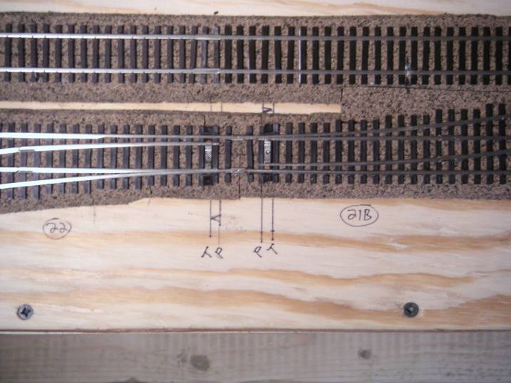 The topside version of the previous picture. The turnout on the right is part of a mainline crossover, while the switch
on the left joins the Cross Cut Secondary Track (the short side of the Castle wye) to the mainline.
The topside version of the previous picture. The turnout on the right is part of a mainline crossover, while the switch
on the left joins the Cross Cut Secondary Track (the short side of the Castle wye) to the mainline.
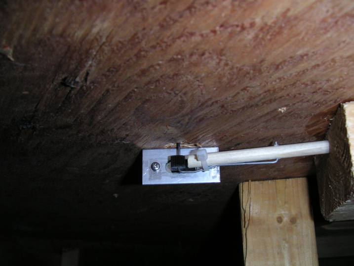
 Two examples of the manual turnout controls, using slide switches and pushrods. The switch is a standard DPDT
slide switch which I bought at Electronic Surplus in Cleveland.
The rods are 1/4" dowel rods which you can buy at any hardware store. The switches are held in place
underneath the throwbar with aluminum brackets that my friend Brad White made for me out of 3/4"
aluminum angle stock. Depending on the circumstances, the wire connection to the pushrod can be made below
or next to the switch. The contacts on the back of the switch are used like the auxiliary contacts on a Tortoise
for power routing to the frog or switch position detection.
Two examples of the manual turnout controls, using slide switches and pushrods. The switch is a standard DPDT
slide switch which I bought at Electronic Surplus in Cleveland.
The rods are 1/4" dowel rods which you can buy at any hardware store. The switches are held in place
underneath the throwbar with aluminum brackets that my friend Brad White made for me out of 3/4"
aluminum angle stock. Depending on the circumstances, the wire connection to the pushrod can be made below
or next to the switch. The contacts on the back of the switch are used like the auxiliary contacts on a Tortoise
for power routing to the frog or switch position detection.
January 25, 2004
This day's highlight was the permanent mounting of the control panel on its cabinet. Two sides, made from 3/4" plywood, were cut at an angle to match the slope of the panel front. These support the panel in addition to its hinges. The side pieces were attached to 2x2 pieces dropped from the top of the benchwork to hold everything together.
 Part of the control panel mountng involved working in tight quarters. Tim Krogg clamps the front 2x2 piece for the left side
of the panel. The rear 2x2 is already mounted and can be seen on the left.
Part of the control panel mountng involved working in tight quarters. Tim Krogg clamps the front 2x2 piece for the left side
of the panel. The rear 2x2 is already mounted and can be seen on the left.
 Tim puts in the screws for the 2x2.
 Fred finishes the job.
January 19, 2004
 The control panel at Castle Tower, temporarily mounted in place. There are no buttons or lights on the control panel
yet, and it need some touch-up paint, but we wanted to put it in place to see where it might interfere with wiring at the west end of Castle interlocking.
The control panel at Castle Tower, temporarily mounted in place. There are no buttons or lights on the control panel
yet, and it need some touch-up paint, but we wanted to put it in place to see where it might interfere with wiring at the west end of Castle interlocking.
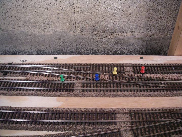 How to properly cut gaps for a crossover. Cut a gap at every colored pushpin, and wire the frogs based on the
auxiliary contacts on your switch machine.
How to properly cut gaps for a crossover. Cut a gap at every colored pushpin, and wire the frogs based on the
auxiliary contacts on your switch machine.
Pictures from 2003 and earlier can be found here.