Erie & Pittsburgh Branch Model Railroad Photos, page 2
This page has pictures from 2003 and before. The most recent photos are at the top.
Other pictures
December 14, 2003
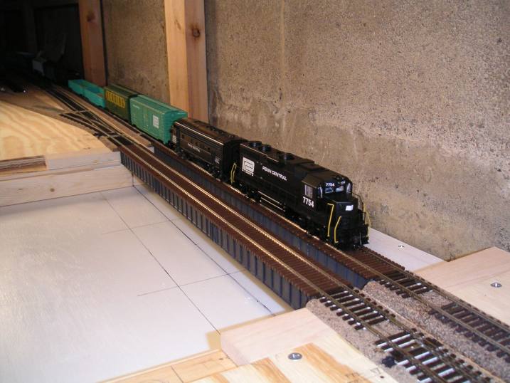 The bridges were finally installed. To celebrate, we posed one of the test trains with a couple locomotives on the
bridge. Unfortunately, they didn't get there on their own power, as the main line still needed to be wired.
The bridges were finally installed. To celebrate, we posed one of the test trains with a couple locomotives on the
bridge. Unfortunately, they didn't get there on their own power, as the main line still needed to be wired.
November 30, 2003
This day was mostly spent on the Mahoning River bridge. The prototype bridge is a four-track, eight or nine span deck girder bridge, although the outer two tracks were abandoned in the 1950's. I originally was going to build this bridge out of Micro Engineering girder bridge kits, but I found that they were both difficult to assemble correctly and not particularly durable. Therefore, my manager at work (who is a woodworker) planed down for me two "bridge cores": pieces of maple which match the inside dimensions of the completed bridge kit. I painted the bridge cores black and then glued the Micro Engineering girders to the sides using Pliobond. The following pictures show the bridge in place and awaiting track.
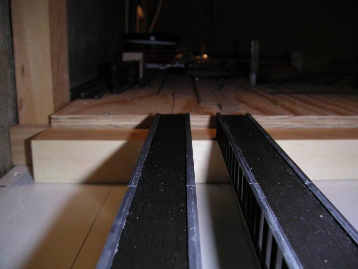
 Here are the two bridges set into position.
 Yes, the bridge abutments needed a little more notched out of them.
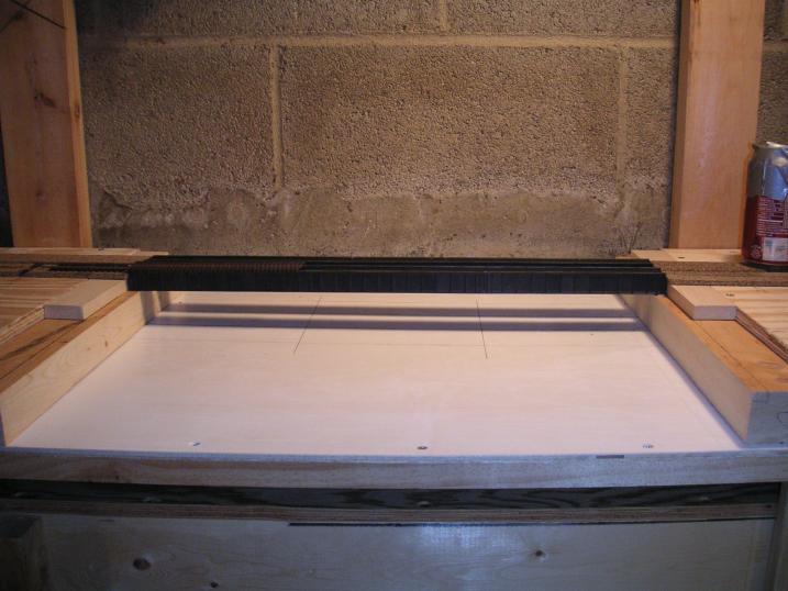
 This overhead view of the bridges looking towards the Castle wye show how the wood pieces fill the interior of the bridge. They were strong enough that we didn't need to install piers yet--that will be done later when the area is sceniced.
November 2, 2003
Once Fred bought a digital camera, it became easier to record the progress of the layout. Besides, Fred likes taking pictures, since, as he says, "electrons are free". The following pictures are from Fred's camera.
 This shows the benchwork for the wye at Castle Tower. The PY&A main line runs along the wall, with the roadbed in the foreground being the connections to the E&P Branch going into New Castle.
The double stack cars that appear in many of these photos are part of one of my test trains that used for testing track and vertical clearances. While double stack cars did not exist during the era I'm modeling (late 1960's), I have a few of them from when I was modeling the modern era, and I decided that I would still like to have the opportunity to run them from time to time. Therefore, the entire layout will be designed with clearances for double stack cars.
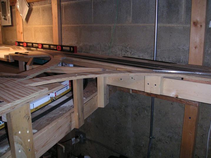 This shows the other side of the benchwork at Castle. The level next to the wall is resting over the riverbed for the
Mahoning River bridge scene.
This shows the other side of the benchwork at Castle. The level next to the wall is resting over the riverbed for the
Mahoning River bridge scene.
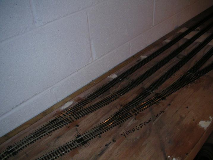 The turnouts at the west (Youngstown) end of the staging yard.
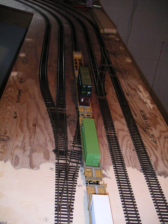 The turnouts in the center of the staging yard. The staging yard has four through tracks for its entire length, and one
track (the 0 track) which entends from here to the west end of the yard only. This set of crossovers and switches is
called "Pittsburgh" and allows trains to pass each other in the staging yard. (The east end switches are
called "Conway".) This is looking what would railroad east at Pittsburgh, which leads around the wall to
"Youngstown". This is where the staging yard tracks figuratively go "around the world" as
anyone knows you can't go east to Youngstown from Pittsburgh without going a long ways out of the way. That's
yard track 0 splitting off to the left, along with the ubiquitous double stack test train cars.
The turnouts in the center of the staging yard. The staging yard has four through tracks for its entire length, and one
track (the 0 track) which entends from here to the west end of the yard only. This set of crossovers and switches is
called "Pittsburgh" and allows trains to pass each other in the staging yard. (The east end switches are
called "Conway".) This is looking what would railroad east at Pittsburgh, which leads around the wall to
"Youngstown". This is where the staging yard tracks figuratively go "around the world" as
anyone knows you can't go east to Youngstown from Pittsburgh without going a long ways out of the way. That's
yard track 0 splitting off to the left, along with the ubiquitous double stack test train cars.
 Roadbed at the east end of Moravia Yard. The yard lead will split off to the right, while the roadbed curving to the
left will be for the Mahoning Valley Sand & Gravel Company (refered to as MVS&G).
Roadbed at the east end of Moravia Yard. The yard lead will split off to the right, while the roadbed curving to the
left will be for the Mahoning Valley Sand & Gravel Company (refered to as MVS&G).
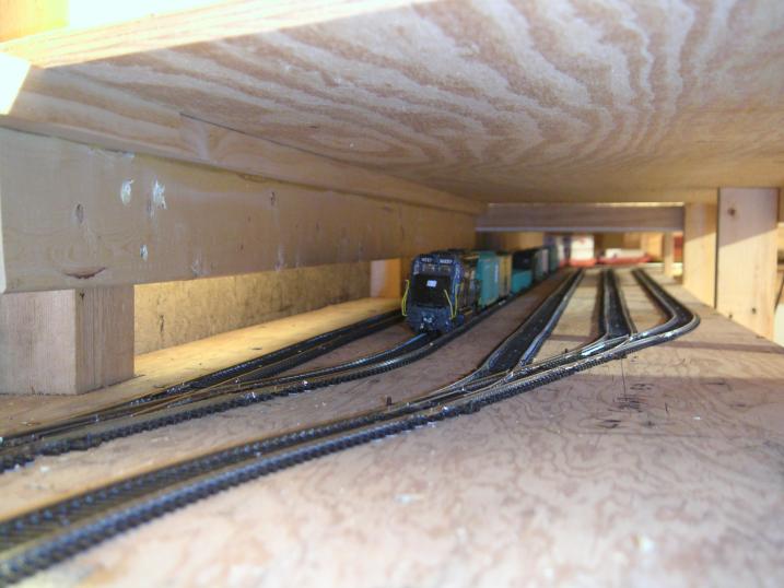 A view east through the staging yard, nicknamed the "subway". The Conway switches are in the
foreground.
A view east through the staging yard, nicknamed the "subway". The Conway switches are in the
foreground.
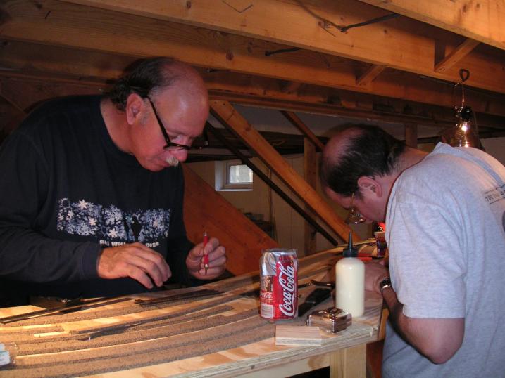 Tim Krogg (left) and I work on roadbed at the east end of Moravia Yard. I'm standing inside the benchwork.
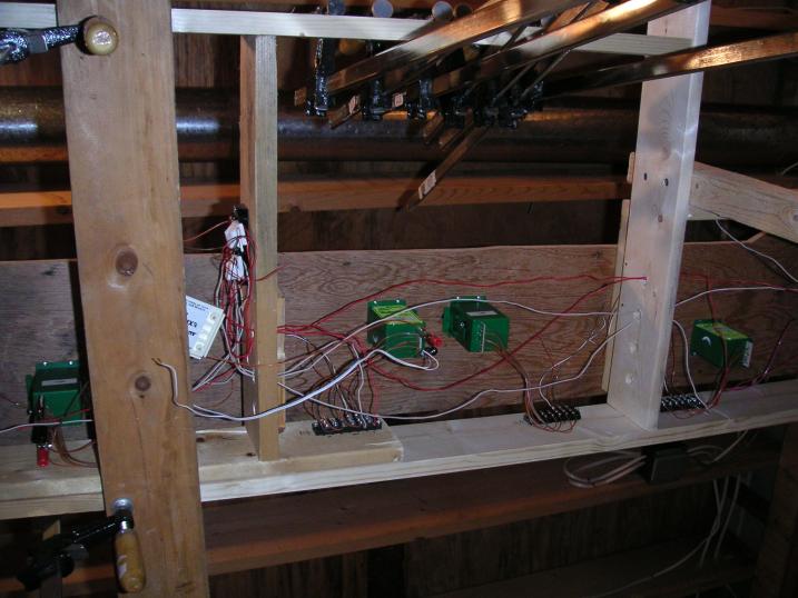 A look a the Tortoise switch machines and wiring underneath the crossovers at Wampum Junction. The black and
chrome objects at the top are clamps which are being stored there. Tortoises are slow-action motor-driven machines
which move the points on the powered turnouts. We prefer these to the snap action of twin-coil machines.
A look a the Tortoise switch machines and wiring underneath the crossovers at Wampum Junction. The black and
chrome objects at the top are clamps which are being stored there. Tortoises are slow-action motor-driven machines
which move the points on the powered turnouts. We prefer these to the snap action of twin-coil machines.
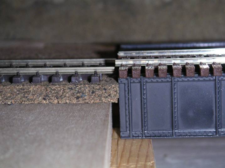
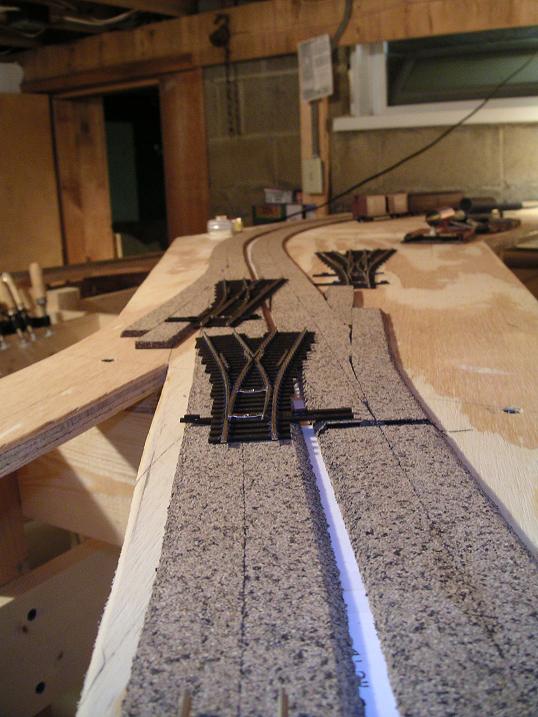
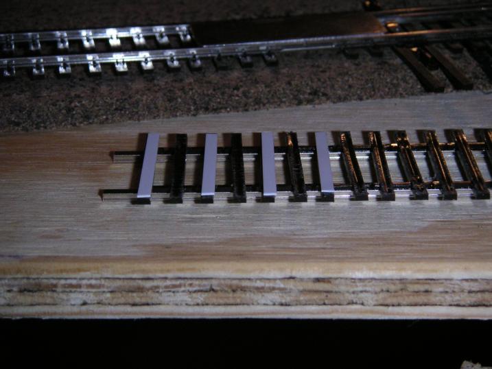 For my track materials, I settled on using Atlas Code 83 flextrack and Walthers Code 83 turnouts on the upper level.
We discovered that the ties on the Walthers turnouts are not as tall as the ties on Atlas track. Therefore, without some
shims, the railheads would not line up properly, even though the rails are the same height. To avoid bumps in the track,
we used .010" strip styrene glued to the bottom of the first few ties on the Walthers track to make sure everything
lined up properly.
For my track materials, I settled on using Atlas Code 83 flextrack and Walthers Code 83 turnouts on the upper level.
We discovered that the ties on the Walthers turnouts are not as tall as the ties on Atlas track. Therefore, without some
shims, the railheads would not line up properly, even though the rails are the same height. To avoid bumps in the track,
we used .010" strip styrene glued to the bottom of the first few ties on the Walthers track to make sure everything
lined up properly.
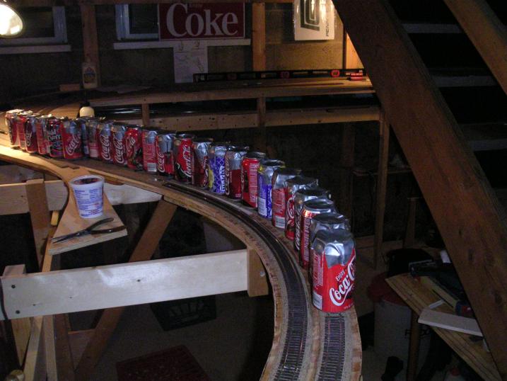 We use Elmer's Wood Glue to affix to track to the cork roadbed. In order to make sure the glue sets up properly,
we weight down the track with pop (some people call it soda) cans filled with playground sand. These weights are
placed side by side along the track for the entire length it is glued down. Here we see some cans weighting down
main line Track 2 at the east end of Moravia Yard.
We use Elmer's Wood Glue to affix to track to the cork roadbed. In order to make sure the glue sets up properly,
we weight down the track with pop (some people call it soda) cans filled with playground sand. These weights are
placed side by side along the track for the entire length it is glued down. Here we see some cans weighting down
main line Track 2 at the east end of Moravia Yard.
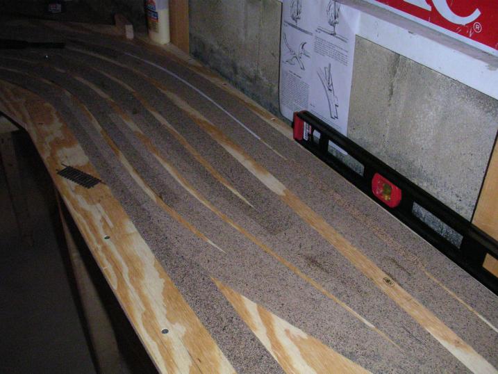 The completed roadbed for the main line and yard tracks at the west end of Moravia Yard. I think the next yard we build will use cork sheets and we can draw out the track centers directly on the cork instead.
February 20, 2002
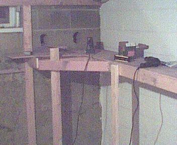
 Benchwork for the Youngstown end of the staging yard.
 Benchwork for the Youngstown end of the staging yard, looking towards the hole in the wall that will carry the E&P
main into the next room. (The hole on the right was half done before I realized it was in the wrong place.)
Benchwork for the Youngstown end of the staging yard, looking towards the hole in the wall that will carry the E&P
main into the next room. (The hole on the right was half done before I realized it was in the wrong place.)